Fuel pump - removal and refitting
Note: Refer to the precautions at the end of Section 1 before proceeding.
Removal
1 The fuel pump is bolted to the underside of
the car just to the rear of the fuel tank. For
access raise and support the car securely at
the rear.
2 Disconnect the battery earth lead.
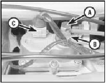
3 On the K-Jetronic system relieve the system pressure by slowly loosening the fuel feed pipe union at the warm-up regulator (see illustration). Absorb the fuel leakage in a cloth.

6.3 Warm-up regulator fuel feed pipe (A), outlet pipe (B) and wiring
multi-plug (C)
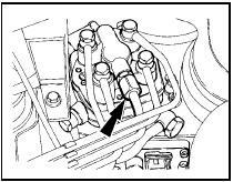
4 On the KE-Jetronic system relieve the system pressure by slowly loosening the cold start valve union on the top of the fuel distributor (see illustration). Absorb fuel leakage in a cloth.

6.4 KE-Jetronic system cold start valve pipe union (arrowed) on fuel
distributor
5 Clamp the fuel inlet hose midway between the tank and the pump using a brake hose clamp, self-locking grips or similar. If the fuel level in the tank is low you may prefer to drain the fuel from the tank into a suitable container once the inlet hose is disconnected.
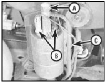
6 Disconnect the fuel inlet and outlet pipes from the pump, catching fuel spillage in a suitable container (see illustration). Once disconnected do not allow dirt to enter the pipes, temporarily plug or seal them if necessary.

6.6 Fuel pump outlet pipe (A), electrical connections (B) and pump bracket
retaining bolt (C)
7 Note the electrical connections to the pump and disconnect them.
8 Loosen the pump bracket retaining bolt and then withdraw the pump unit with rubber protector sleeve.
Refitting
9 Refitting of the fuel pump is a reversal of
the removal procedure. Renew the feed pipe
from the tank if it is damaged or defective.
10 Check that the rubber protector sleeve is correctly positioned round the pump before tightening the clamp nut.
11 On completion, tighten the warm-up regulator or cold start valve fuel unions, reconnect the battery earth lead, start the engine and check for any fuel leaks.
See also:
Specifications
System type . . . . . . . . . . . . . . . . . . . . . . . . . .
. . . . . . . . . . . . . . . . . 12 volt, negative earth
Bulbs Wattage
Headlamp:
Halogen . . . . . . . . . . . . . . . . . . . . . ...
Trip computer components - removal and refitting
1 Disconnect the battery negative lead
Computer module
2 Remove the single screw from the top edge
of the facia panel in which the module is
housed, then withdraw the facia panel.
3 Remove the fo ...
Fuel system (1.6 and 1.8 litre (R6A type) CVH) - depressurisation
Remember to depressurise the
fuel system before loosening any
connections.
Refer to the precautions in
Section 1 before proceeding. The fuel
system will remain pressurised after the
engine is sw ...
