Fuel-injection control module - removal and refitting
Removal
1 The fuel-injection control module is only
used on KE-Jetronic systems and is located in
the engine compartment behind the heater
plenum chamber and fan motor.
2 Disconnect the battery negative lead.
3 Remove the plenum chamber top cover rubber seal (see illustration).
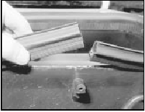
16.3 Remove the plenum chamber rubber seal
4 Release the five retaining clips and lift off the plenum chamber top cover (see illustrations).
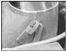
16.4a Release the retaining clips . . .
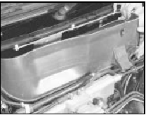
16.4b . . . and lift off the plenum chamber top cover
5 Undo the two nuts securing the heater fan motor assembly to the bulkhead. Lift the unit off the studs and place it on the engine, but avoid straining the wiring (see illustrations).
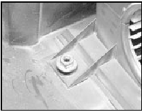
16.5a Heater fan motor retaining nut
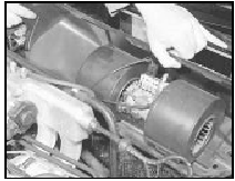
16.5b Removing the heater fan motor assembly . . .
6 Disconnect the module wiring multi-plug, then undo the three screws and remove the unit from its location (see illustration).
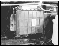
16.6 . . . for access to the fuel-injection control module
Refitting 7 Refitting is the reversal of removal. Take care not to trap the motor wiring when refitting the fan motor assembly and ensure that it is engaged in the slot provided in the housing (see illustration).
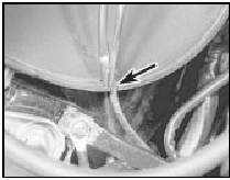
16.7 Fan motor wiring engaged in housing slot (arrowed)
See also:
Timing belt and sprockets - removal and refitting
Note: Refer to the warning in Section 8 before
proceeding. On models from mid-1985
(without a timing belt tensioner spring) the belt
tension should be checked using Ford special
tool No 21-113 aft ...
Engine - removal leaving automatic transmission in vehicle
Note: Refer to the warning in Section 8 before
proceeding. A suitable hoist and lifting tackle
will be required for this operation.
1 Proceed as described in Section 9,
paragraphs 1 to 17 inclusiv ...
Diagram 2: 1980-86 Lighting all models
Diagram 2: 1980-86 Lighting all models ...
