Instrument panel components - removal and refitting
Panel illumination and warning
lamp bulbs
Removal
1 Remove the instrument panel as described
in Section 9.
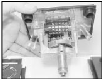
2 Turn the bulbholders anti-clockwise and remove them from the rear of the instrument panel (see illustration).
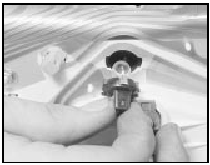
10.2 Instrument panel bulb renewal
3 The bulbs and bulbholders are renewed complete, the bulbs cannot be removed from the holders separately.
Refitting
4 Refit by pushing down and turning
clockwise.
Printed circuit
Removal
5 Remove the instrument panel (Section 9).
6 Remove all illumination and warning lamp bulbholders.
7 Undo all the nuts and remove the washers from the printed circuit terminals.
8 Remove the wiring multi-plug retainers and carefully pull the printed circuit off the pins on the rear of the panel.
Refitting
9 Refitting is the reverse sequence to
removal.
Speedometer
Removal
10 Remove the instrument panel as
described in Section 9.
11 Undo the retaining screws around the edge of the panel at the rear and separate the two panel halves (see illustrations).
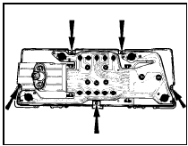
10.11a Instrument panel assembly retaining screws-pre-1986 models
10.11b Instrument panel assembly upper retaining screws - 1986 models onwards
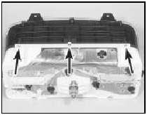
12 Undo the two screws and remove the speedometer (see illustrations).
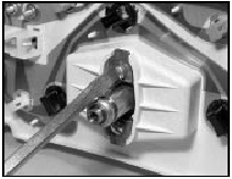
10.12a Extracting speedometer retaining screws
10.12b Removing the speedometer
Refitting 13 Refitting is the reverse sequence to removal.
Tachometer
14 The procedure is the same as for the
speedometer except that the unit is secured
by three nuts.
Fuel and temperature gauges 15 Proceed as for the speedometer but remove the combined gauge assembly after undoing the four nuts.
See also:
Electronic modules - removal and refitting
Note: Refer to Section 1 for precautions to be
observed when working with electronic
modules.
1 Disconnect the battery negative lead.
All ESC modules except ESC
(early “Economy” models)
2 All mo ...
Accelerator pedal - removal and refitting
The procedure is the same as described in
Part A of this Chapter for carburettor models. ...
Throttle housing - removal and refitting
Note: A new gasket must be used on refitting.
Removal
1 Disconnect the battery negative lead.
2 Depressurise the fuel system as described
in Section 6.
3 Remove the air inlet pipe (see illustrati ...
