Pistons and connecting rods - removal and refitting
1.8 litre (R2A type)
Removal
1 With the engine removed from the vehicle,
remove the sump and the cylinder head.
2 Check the big-end caps for identification marks and if necessary use a centre-punch to identify the caps and connecting rods (see illustration).
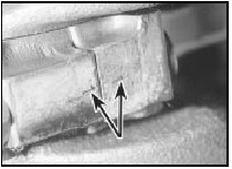
30.2 Big-end cap and connecting rod identification marks (arrowed) - 1.8
litre (R2A)
3 Turn the crankshaft so that No 1 crankpin is at its lowest point, then unscrew the nuts or bolts and tap off the cap. Keep the bearing shells in the cap and connecting rod.
4 Using the handle of a hammer, push the piston and connecting rod up the bore and withdraw from the top of the cylinder block.
Loosely refit the cap to the connecting rod.
5 Repeat the procedure in paragraphs 3 and 4 on No 4 piston and connecting rod, then turn the crankshaft through half a turn and repeat the procedure on Nos 2 and 3 pistons and connecting rods.
Refitting
6 Commence refitting as follows.
7 Clean the backs of the bearing shells and the recesses in the connecting rods and bigend caps.
8 Press the bearing shells into the connecting rods and caps in their correct positions and oil them liberally. Note that the lugs must be adjacent to each other (see illustration).
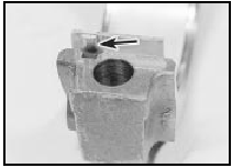
30.8 Bearing shell lug (arrowed) must engage with groove in big-end cap - 1.8
litre (R2A)
9 Lubricate the cylinder bores with engine oil.
10 Fit a ring compressor to No 1 piston then insert the piston and connecting rod into No 1 cylinder. With No 1 crankpin at its lowest point, drive the piston carefully into the cylinder with the wooden handle of a hammer, and at the same time guide the connecting rod onto the crankpin. The piston must be fitted with the cut-out in the piston crown (and the lug on the piston skirt), facing the front of the engine, with the oil hole in the connecting rod on the inlet manifold side of the engine (see illustrations).
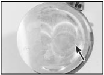
30.10a Cut-out (arrowed) in piston crown . . .
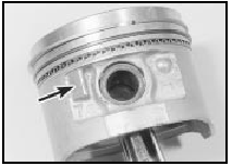
30.10b . . . and lug (arrowed) on piston skirt must face the front of the
engine
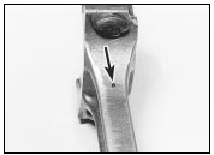
30.10c Connecting rod oil hole (arrowed) must face inlet manifold side of
engine - 1.8 litre (R2A)
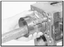
30.10d Fitting a piston and connecting rod into the cylinder bore - 1.8 litre
(R2A)
11 Oil the crankpin, then fit the big-end bearing cap in its previously noted position, and tighten the nuts or bolts to the specified torque.
12 Check that the crankshaft turns freely.
13 Repeat the procedure given in paragraphs 11 to 12 inclusive on the remaining pistons.
14 Refit the cylinder head and the sump.
1.6 and 1.8 litre (R6A type) 15 The procedure is as described above, noting the following points: a) On the 1.6 litre engine, when refitting a piston/connecting rod assembly, the piston must be fitted with the arrow on the piston crown and the cast pip on the piston skirt facing the front (timing belt end) of the engine (see illustration).
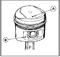
30.15 The arrow (A) and the cast pip (B) must face the front of the engine -
1.6 litre
b) On the 1.6 litre engine, the big-end bearing caps locate on dowels in the connecting rods, and can only be fitted in one position.
See also:
Central door locking components - operation, removal and refitting
Note: If a central locking solenoid or motor is
to be renewed due to jamming or overheating,
the central locking relay must be renewed at
the same time even if it is believed to be
working correct ...
Door mirror - removal and refitting
Manually-operated mirror
1 On remote-control type mirrors, unscrew
the bezel from the adjuster knob (see
illustration).
29.1 Unscrew the bezel from the adjuster knob . . .
2 Prise the mirror tr ...
Ignition switch and lock barrel - removal and refitting
Removal
1 Disconnect the battery negative lead.
2 For improved access, remove the securing
screws and unclip the lower and upper
steering column shrouds.
3 Insert the ignition key and turn to pos ...
