Fuel pump - testing
Caution: Refer to the precautions in Section 1 before proceeding.
Mechanical pump
1 On SOHC engines, the fuel pump is located
on the left-hand side of the cylinder block,
next to the oil filter. On CVH engines the fuel
pump is located on the rear right-hand corner
of the cylinder head.
2 To test the pump, disconnect the ignition coil LT “-/1” lead to prevent the engine from firing.
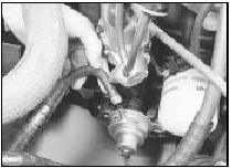
3 Disconnect the outlet hose from the pump, and place a wad of rag next to the pump outlet (see illustration). Take appropriate fire precautions.

7.3 Disconnecting outlet hose from fuel pump - SOHC model
4 Have an assistant crank the engine on the starter motor, and check that well-defined spurts of petrol are ejected from the fuel pump outlet. If not, the pump is faulty.
Dispose of the petrol-soaked rag safely.
5 On some early pumps, the top cover can be removed for access to the filter. Removing the pump and cleaning the filter may cure the problem. On models with a sealed pump, or where cleaning the interior of the pump and filter does not solve the problem, the pump should be renewed, as no spares are available. Check that there is petrol in the fuel tank before condemning the pump!
6 On completion of the test, reconnect the outlet hose to the pump. If the hose was originally secured with a crimped type clip, discard this and use a new worm drive clip.
Reconnect the coil LT lead.
Electric pump
SOHC and CVH models with air
conditioning
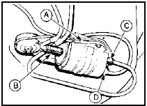
7 The fuel pump is located under the rear of
the vehicle, next to the fuel tank (see
illustration).

7.7 Electric fuel pump - SOHC and CVH models with air conditioning
A Clamping bracket
B Fuel inlet
C Fuel outlet
D Wiring plug
8 If the pump is functioning, it should be possible to hear it “buzzing” by listening under the rear of the vehicle when the ignition is switched on.
9 If the pump appears to have failed completely, check the fuse and relay.
10 To test the pump, disconnect the fuel supply hose from the pressure regulator or vapour separator (as applicable) in the engine compartment. Lead the hose into a measuring cylinder.
11 Take appropriate fire precautions, then switch on the ignition for 30 seconds (do not start the engine), and measure the quantity of petrol delivered: it should be at least 400 ml (0.7 pint). If not, the pump is faulty and should be renewed, as no spares are available.
12 On completion of the test, reconnect the hose to the pressure regulator or vapour separator, as applicable, and if the hose was originally secured with a crimped type clip, discard this and fit a new worm drive clip.
2.0 litre DOHC models
13 If the fuel pump is functioning, it should
be possible to hear it “buzzing” by listening
under the rear of the vehicle when the ignition
is switched on. Unless the engine is started,
the fuel pump should switch off after
approximately one second.
14 If the pump appears to have failed completely, check the appropriate fuse and relay, and where applicable check the state of the fuel pump inertia cut-off switch as follows.
15 The inertia cut-off switch is located in the spare wheel well. The switch incorporates a reset button, which should normally be in the depressed position. Check the position of the reset button before assuming that a fault exists in the fuel pump.
16 To test the fuel pump, special equipment is required, and it is recommended that any suspected faults are referred to a Ford dealer.
See also:
Air Charge Temperature (ACT) sensor - removal and refitting
Removal
1 The air charge temperature sensor is
screwed into the inlet manifold (see
illustration).
14.1 Air charge temperature sensor - 1.6 EFI engine
A Wiring plug B Sensor
2 Disconnect the b ...
Identifying components in the engine compartment
2.0L DOHC Zetec engine
Transmission fluid dipstick (automatic transaxle)
Battery
Air filter assembly
Engine oil filler cap
Engine oil dipstick
Power steering fluid reservoir
Engine ...
Weber 2V carburettor automatic choke unit - adjustment
XR3 models
1 Remove the air cleaner as described in
Section 2.
2 Disconnect the electrical lead to the
automatic choke.
3 Unscrew and remove the three screws
which hold the automatic choke housi ...
