Hydraulic unit pump and motor (ABS) - removal and refitting
Note: New sealing washers must be used on the high pressure fluid hose banjo union, and a new O-ring must be used between the accumulator and the hydraulic unit on refitting.
Caution: Refer to the
precautions in Section 1.
Removal
1 Remove the accumulator.
2 Prepare a suitable container to catch spilt fluid, and disconnect the high pressure fluid hose from the pump.
3 Remove the securing spring clip and disconnect the low pressure fluid hose from the pump. Allow the fluid to drain out of the hose into the container. If fluid is accidentally spilt on the paintwork, wash off immediately with cold water.
4 Disconnect the multi-plugs from the pressure switch and the pump motor.
5 Remove the pump mounting bolt (see illustration).
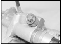
18.5 Hydraulic unit pump mounting bolt - ABS
6 Pull the pump and motor assembly off the mounting spigot and remove it.
7 Recover the mounting bushes and renew them if necessary.
8 If a new pump is to be fitted, transfer the pressure switch to it, using a new O-ring.
Refitting
9 Commence refitting by offering the pump to
the mounting spigot, then reconnecting the
low pressure fluid hose.
10 Refit and tighten the pump mounting bolt.
11 Reconnect the high pressure fluid hose, using new sealing washers on the banjo union.
12 Refit the accumulator, using a new O-ring.
13 Reconnect the multi-plugs and the battery.
14 Refill the fluid reservoir, then switch on the ignition and allow the pump to prime itself.
Allow the pump to run for a maximum of two minutes at a time then leave it for ten minutes to cool down.
15 On completion, bleed the complete hydraulic system and check for leaks around all disturbed components.
See also:
Auxiliary warning system components - removal and refitting
General
1 This system monitors the fluid levels and
front brake pads for excessive wear. In the
event of a fluid level dropping below the
specified level, or the brake pads wearing
down to the mi ...
Specifications
General
System type . . . . . . . . . . . . . . . . . . . . . . . . . . . . . . . . . .
. . . . . . . . . . . . Multi-point electronic fuel injection
Application . . . . . . . . . . . . . . . . . ...
Engine - refitting (automatic transmission in vehicle)
1 Reverse the procedure in paragraphs 1 to
10 of Section 6, noting the following points.
2 Check that the engine adapter plate is
correctly positioned on its locating dowels. If
necessary, a cable ...
