Front suspension strut - removal, overhaul and refitting
Note: A spring compressor tool will be required if the strut is to be dismantled.
Removal
1 Loosen the relevant front roadwheel nuts,
apply the handbrake, jack up the front of the
vehicle and support on axle stands (see
“Jacking and Vehicle Support”).
2 Remove the roadwheel. On P100 models mark the position of the roadwheel in relation to one of the wheel studs before removal.
3 Remove the front brake caliper but do not disconnect the hydraulic hose. Support the caliper on an axle stand to avoid straining the hose.
4 Where applicable, unbolt the ABS wheel sensor from the hub carrier and detach the wire from the clip on the strut. Unplug the connector and place the sensor to one side.
5 Unscrew and remove the pinch-bolt which secures the hub carrier to the strut. Using a suitable lever, such as a cold chisel, lever the hub carrier clamp legs and wedge them apart.
6 Lever the suspension lower arm downwards to separate the hub carrier from the bottom of the strut.
7 Working in the engine compartment, unscrew the strut upper mounting nut, at the same time supporting the strut from below.
Use a 6 mm Allen key inserted in the end of the strut piston rod to prevent the rod from turning as the upper mounting nut is unscrewed (see illustration). On some models, the upper mounting nut may be fitted with a plastic cover. Note the upper mounting cup under the nut.
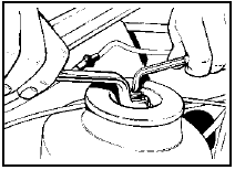
4.7 Hold the strut piston rod with a 6 mm Allen key when unscrewing the upper
mounting nut
8 Withdraw the strut from under the wing of the vehicle.
Overhaul
9 To dismantle the strut, proceed as follows.
10 Using spring compressors, compress the coil spring. Do not attempt to compress the spring without using purpose-made spring compressors, as the spring is under considerable tension, and personal injury may occur if it is suddenly released (see illustration).
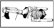
4.10 Suspension strut fitted with spring compressors
11 Hold the piston rod as described in paragraph 7, unscrew the nut from the piston rod and remove the lower cup, bearing, spring seat, gaiter, coil spring and bump stop (see illustration).
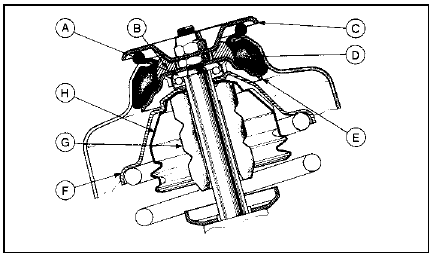
4.11 Cross-section of the front strut upper mounting
A Bearing
B Nylon spacer
C Upper cup
D Rubber insulator
E Lower cup
F Spring seat
G Bump stop
H Gaiter
12 Working in the engine compartment, remove the upper cup and nylon spacer, and if required prise out the rubber insulator.
13 Clean all the components and examine them for wear and damage. Check the action of the shock absorber by mounting it vertically in a vice and operating the piston rod several times through its full stroke. If any uneven resistance is evident, the shock absorber must be renewed. Renew any worn or damaged components as applicable.
Refitting
14 Reassembly and refitting is a reversal of
dismantling and removal, bearing in mind the
following points.
15 When reassembling, ensure that the gaiter is fitted over the bump stop, and that the ends of the coil spring are correctly located on the spring seats. Also ensure that the bearing is correctly located on the upper spring seat.
16 Fit the nylon spacer over the piston rod before fitting the strut to the top mounting.
17 Tighten all fixings to the specified torque.
18 On P100 models align the previously made marks on the roadwheel and wheel stud.
See also:
Heating and ventilation system - description
The heater is of the type which utilises
waste heat from the engine coolant. The
coolant is pumped through the matrix in the
heater casing where air, force-fed by a duplex
radial fan, disperses th ...
General information
All models utilise a light alloy inlet manifold
which on carburettor models is coolant
heated to improve the atomisation of the
fuel/air mixture.
The exhaust manifold is of cast iron
construction ...
Identifying components in the engine compartment
2.0L DOHC Zetec engine
Transmission fluid dipstick (automatic transaxle)
Battery
Air filter assembly
Engine oil filler cap
Engine oil dipstick
Power steering fluid reservoir
Engine ...
