Manual transmission oil level check (Every 12 000 miles or 12 months)
1 With the car on level ground wipe the area around the filler plug, then unscrew the plug using a socket spanner, or on later versions a suitable Torx or Allen key or socket bit, as applicable. Access can be gained from above or below the car (see illustrations).
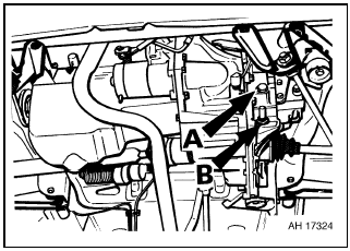
26.1a Transmission oil filler plug (A) and selector shaft locking mechanism
cap (B)
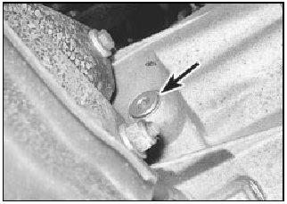
26.1b Allen type transmission filler plug (arrowed) as fitted to later models
2 Locate the aluminium build code tag, which is secured to one of the transmission housing upper bolts, and note the transmission part number stamped on the tag. If the last letter of the part number suffix is a D then the transmission was manufactured prior to August 1985. Transmissions manufactured from August 1985 have an E as the last letter of the part number suffix.
3 On the early type transmission (suffix letter D) the oil level must be maintained between 5 and 10 mm (0.2 and 0.4 in) below the lower edge of the filler plug hole.
4 If the transmission is of the later type (suffix letter E) the oil level must be maintained between 0 and 5 mm (0.2 in) below the lower edge of the filler plug hole.
5 To simplify the checking procedure a dipstick can be made from thin rod bent at right angles and having marks on one “leg” made with a file at 5 mm (0.2 in) intervals. Rest the unmarked leg on the lower edge of the filler plug hole with the marked leg immersed in the oil. Remove the dipstick, read off the level and top-up if necessary using the specified grade of oil. Refit the filler plug on completion.
6 Renewal of the transmission oil is not a service requirement, but if draining is necessary prior to a repair or overhaul task place a suitable container beneath the selector shaft locking mechanism cap nut located just below the filler plug (see illustration). Unscrew the cap nut, remove the spring and interlock pin and allow the oil to drain.
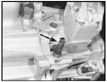
26.6 Selector shaft locking mechanism cap nut (arrowed)
Caution: Take care when unscrewing the cap nut as the tension of the spring may cause the pin to fly out as the cap nut is released. Refit the pin, spring and cap nut when draining is complete, but apply sealer to the cap nut threads (see Specifications). Note that from 1986 onwards the cap nut is shrouded by the transmission support crossmember and cannot be removed in situ. On these models draining can only be carried out after removal of the transmission from the car.
See also:
Heated rear window aerial amplifier - removal and refitting
Removal
1 On some 1986 models onwards the radio
aerial is incorporated in the heated rear
window element, and to assist reception an
amplifier is fitted. This is located in the tailgate
adjacent ...
Steering wheel - removal and refitting
Removal
1 According to model, either pull off the
steering wheel trim, prise out the insert which
carries the Ford motif at the centre, or carefully
prise up and lift off the horn push followed by ...
Hydraulic unit pressure switch (ABS) - removal and refitting
Note: To remove the pressure switch from the
hydraulic unit in situ, Ford tool No 12-008 or a
locally made equivalent will be required. The
switch may be removed without special tools
after removi ...
