Air cleaner air temperature control - description and testing
Thermostatically-controlled air
cleaner
1 On all pre-1986 models and certain models
from 1986 onwards, the air cleaner is
thermostatically-controlled by a vacuum
operated system to provide air at the most
suitable temperature for combustion with
minimum emission levels.
2 This is accomplished by drawing in cold air from an inlet at the front of the car, and hot air from a collector box on the exhaust manifold and blending them. The proportion of hot and cold air is varied by the position of a flap valve in the inlet spout which itself is controlled by a vacuum diaphragm. The vacuum pressure is regulated by a heat sensor located within the air cleaner body to ensure that the appropriate degree of inlet manifold vacuum is applied to the flap valve, thus maintaining the air temperature within the preset limits.
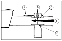
3 To check the thermostatic control of the air cleaner the engine must be cold. First observe the position of the flap valve which should be fully closed prior to starting the engine (see illustration).

3.3 Thermostatically controlled air cleaner operation under low vacuum
conditions
A Vacuum hose to heat sensor
B Vacuum diaphragm
C Diaphragm
D Flap valve closed
F Cold air inlet
The flap valve can be observed using a mirror after disconnecting the inlet hose.
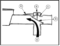
4 Start the engine and check that the flap valve opens fully at idle speed to allow only hot air from the manifold to enter the air cleaner (see illustration).

3.4 Thermostatically-controlled air cleaner operation under high vacuum
conditions
A Vacuum hose to heat sensor
B Vacuum diaphragm
C Diaphragm
D Flap valve open
E Hot air inlet
5 Should the flap valve remain in the closed position once the engine is started, then the diaphragm unit or the heat sensor is at fault and should be tested to isolate the defective unit.
6 Make sure that all vacuum lines are secure and free from leaks as a final check.
7 To check the operation of these components a vacuum pump is required. If one is available proceed as follows, if not, have the tests carried out by a dealer.
8 Detach the diaphragm-to-heat sensor vacuum line at the sensor end and connect a vacuum pump to the diaphragm unit. Apply a vacuum up to 100 mm (4.0 in) of mercury and retain this whilst checking the flap valve.
9 If the flap valve is now open, then the heat sensor is faulty and must be renewed. If the valve remains shut, the diaphragm unit is faulty and a new air cleaner will have to be obtained, as the diaphragm unit is not available separately.
10 After the checks, disconnect the vacuum pump and reconnect the vacuum line and inlet hose.
Waxstat-controlled air cleaner 11 From 1986 onwards the waxstat type air cleaner is being progressively introduced to replace the thermostatically-controlled type used previously.
12 The waxstat air cleaner performs the same hot and cold air blending operation using a flap valve as described previously, but the flap valve is controlled by a wax capsule and is not dependent on manifold vacuum.
13 When the engine is cold the wax in the capsule contracts and the flap valve is pulled back to shut off the cold air inlet. As engine ambient temperature rises the wax expands and the flap is opened to admit only cold air into the air cleaner.
14 To test the unit the engine must initially be cold.
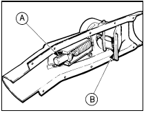
15 Remove the manifold-to-air cleaner hot air hose and observe the position of the flap valve which should be open to allow only hot air to enter (see illustration).

3.15 Waxstat type air cleaner components in air cleaner spout
A Wax capsule B Flap valve
16 Refit the hose and warm up the engine to normal operating temperature.
17 Remove the hot air hose again and check the position of the flap valve. With the engine at normal operating temperature the flap should be closed to admit only cold air into the air cleaner.
18 If this is not the case the waxstat is defective and the air cleaner must be renewed as the waxstat is not available separately.
19 Refit the hot air hose on completion of the checks.
See also:
Routine maintenance and servicing
Ford Sierra maintenance schedule
The maintenance intervals in this manual
are provided with the assumption that you will
be carrying out the work yourself. These are
the minimum maintenance interv ...
Carburettor (Ford VV type) - removal and refitting
Caution: Refer to the
precautions in Section 1 before
proceeding.
Note: A new gasket must be used when
refitting the carburettor. A tachometer and an
exhaust gas analyser will be required to chec ...
Radio/cassette player - removal and refitting
Standard fixing
1 Disconnect the battery negative lead.
2 Pull off the two control knob assemblies.
3 Release the trim panel by unscrewing the
two securing nuts from the control spindles.
Remove ...
