Instrument panel components - removal and refitting
1 Remove the instrument panel.
Panel illumination and warning
lamp bulbs
2 Twist the relevant bulbholder anticlockwise
and withdraw it from the printed
circuit board on the rear of the instrument
panel.
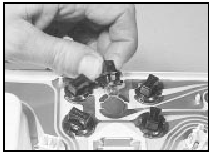
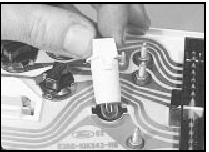
3 The bulbs may be either a push-fit in the bulbholder, or integral with the bulbholder in which case the bulb and bulbholder must be renewed as a unit (see illustrations).

21.3a Removing an instrument panel warning lamp bulb - bulb is a push-fit in
the bulbholder

21.3b Removing an instrument panel illumination bulb - bulb is integral with
bulbholder
4 Refitting is a reversal of removal.
Panel lens
5 Remove the three upper and three lower
securing screws and withdraw the lens from
the instrument panel.
6 Refitting is a reversal of removal, but ensure that the two locating pegs on the upper corners of the instrument panel protrude through the lens, and locate the lugs on the lower edge of the lens in the cut-outs in the instrument panel.
Printed circuit board
7 Using a thin-bladed screwdriver, unclip and
remove the wiring plug socket.
8 Remove all the illumination and warning lamp bulbs as described earlier in this Section.
9 Remove all the nuts and washers from the printed circuit board terminals.
10 Unclip the printed circuit board from the retainers at the back of the instrument panel, and carefully withdraw the board over the terminal pins on the gauges.
11 Refitting is a reversal of removal.
Speedometer
12 Remove the panel lens (paras. 5 and 6).
13 Remove the two screws securing the speedometer to the rear of the instrument panel, taking care not to lose the two brushes.
Withdraw the speedometer through the front of the instrument panel.
14 Refitting is a reversal of removal.
Tachometer
Models up to 1990
15 Remove the four or five securing screws,
as applicable, and separate the two halves of
the instrument panel housing.
16 Remove the three securing nuts and washers from the rear of the instrument panel housing, and withdraw the tachometer.
17 Refitting is a reversal of removal, but ensure that the tachometer engages with the locating ribs in the housing around the dial edge.
Models from 1990
18 The procedure is as described above but
before the tachometer can be withdrawn from
the instrument panel housing, the printed circuit
board must be carefully pulled from the
tachometer terminals. Ensure that the printed
circuit board is pushed fully home when refitting.
Fuel and temperature gauges
Models up to 1987
19 Remove the four securing screws and
separate the two halves of the instrument
panel housing.
20 Remove the four securing nuts and washers from the rear of the instrument panel housing, and withdraw the combined gauge assembly.
21 Refitting is a reversal of removal.
Models from 1987
22 Remove the five securing screws and
separate the two halves of the instrument
panel housing.
23 Remove the printed circuit board as described previously in this Section.
24 On “low specification” models, remove the two securing screws from the front of the gauge assembly, then withdraw the combined gauge assembly from the printed circuit board.
25 On “high specification” models, simply withdraw the combined gauge assembly from the printed circuit board.
26 Refitting is a reversal of removal, but on “high specification” models, ensure that the gauge assembly engages with the locating ribs in the housing around the gauge edge.
See also:
Carburettor (Weber 2V type) - fast idle speed adjustment
1 This procedure does not apply to models
fitted with a carburettor stepper motor, for
which no adjustment is possible.
2 Check the idle speed and mixture. The idle
speed must be correct before at ...
Cylinder head - inspection and renovation
Note: On engines fitted with hardened valve
seats for use with unleaded petrol, valve and
valve seat grinding and recutting cannot be
carried out without the use of specialist
equipment. Consult a ...
Throttle body - removal and refitting
Note: A tachometer and an exhaust gas
analyser will be required to check the idle
mixture on completion. A new gasket must be
used when refitting the throttle body.
2.0 litre SOHC models
1 Discon ...
