Examination and renovation
1 Clean all components using paraffin and a stiff brush, except the crankshaft, which should be wiped clean and the oil passages cleaned out with a length of wire.
2 Never assume that a component is unworn simply because it looks all right. After all the effort which has gone into dismantling the engine, refitting worn components will make the overhaul a waste of time and money.
Depending on the degree of wear, the overhauler’s budget and the anticipated life of the vehicle, components which are only slightly worn may be refitted, but if in doubt it is always best to renew.
Crankshaft, main and big-end
bearings
3 The need to renew the main bearing shells
or to have the crankshaft reground will usually
have been determined during the last few
miles of operation when perhaps a heavy
knocking has developed from within the
crankcase or the oil pressure warning lamp
has stayed on denoting a low oil pressure
probably caused by excessive wear in the
bearings.
4 Even without these symptoms, the journals and crankpins on a high mileage engine should be checked for out-of-round (ovality) and taper. For this a micrometer will be needed to check the diameter of the journals and crankpins at several different points around them. A motor factor or engineer can do this for you. If the average of the readings shows that either out-of-round or taper is outside permitted tolerance (see Specifications), then the crankshaft should be reground by your dealer or engine reconditioning company to accept the undersize main and big-end shell bearings which are available. Normally, the company doing the regrinding will supply the necessary undersize shells.
5 If the crankshaft is in good condition, it is wise to renew the bearing shells as it is almost certain that the original ones will have worn.
This is often indicated by scoring of the bearing surface or by the top layer of the bearing metal having worn through to expose the metal underneath.
6 Each shell is marked on its back with the part number. Undersize shells will have the undersize stamped additionally on their backs.
7 Standard size crankshafts having main bearing journal diameters at the lower end of the tolerance range are marked with a yellow spot on the front balance weight. You will find that with this type of crankshaft, a standard shell is fitted to the seat in the crankcase but a yellow colour-coded shell to the main bearing cap (see illustrations).
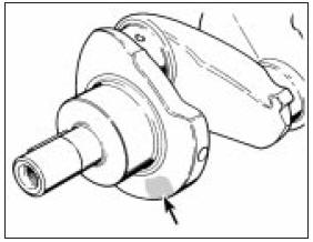
13.7a Crankshaft main bearing journal size identification mark on balance web
(arrowed)
13.7b Bearing shell colour identification markings (arrowed)
8 If a green spot is seen on the crankshaft then this indicates that 0.25 mm (0.0098 in) undersize big-end bearings are used (see illustration).
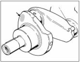
13.8 Crankshaft big-end journal size identification mark on crank throw web
Cylinder bores, pistons, rings and
connecting rods
9 Cylinder bore wear will usually have been
evident from the smoke emitted from the
exhaust during recent operation of the vehicle
on the road, coupled with excessive oil
consumption and fouling of spark plugs.
10 Engine life can be extended by fitting special oil control rings to the pistons. These are widely advertised and will give many more thousands of useful mileage without the need for a rebore, although this will be inevitable eventually. If this remedy is decided upon, remove the piston/connecting rods (Section 8) and fit the proprietary rings in accordance with the manufacturer’s instructions.
11 Where a more permanent solution is decided upon, the cylinder block can be rebored by your dealer or engineering works, or by one of the mobile workshops which now undertake such work. The cylinder bore will be measured both for out-of-round and for taper to decide how much the bores should be bored out. A set of matching pistons will be supplied in a suitable oversize to suit the new bores.
12 Due to the need for special heating and installing equipment for removal and refitting of the interference type gudgeon pin, the removal and refitting of pistons to the connecting rods is definitely a specialist job, preferably for your Ford dealer.
13 The removal and refitting of piston rings is however well within the scope of the home mechanic. Do this by sliding two or three old feeler blades round behind the top compression ring so that they are at equidistant points. The ring can now be slid up the blades and removed. Repeat the removal operations on the second compression ring and then the oil control ring.
This method will not only prevent the rings dropping onto empty grooves as they are withdrawn, but it will also avoid ring breakage.
14 Even when new piston rings have been supplied to match the pistons, always check that they are not tight in their grooves and also check their end gaps by pushing them squarely down their particular cylinder bore and measuring with a feeler blade (see illustration). Adjustment of the end gap can be made by careful grinding to bring it within the specified tolerance.
13.14 Checking piston ring end gap
15 If new rings are being fitted to an old piston, always remove any carbon from the grooves beforehand. The best tool for this job is the end of a broken piston ring. Take care not to cut your fingers, piston rings are sharp.
The cylinder bores should be roughened with fine glass paper to assist the bedding-in of the new rings.
Timing sprockets and chain 16 The teeth on the timing sprockets rarely wear, but still check for broken or hooked teeth.
17 The timing chain should always be renewed at time of major engine overhaul. A worn chain is evident if when supported horizontally at both ends it takes on a deeply bowed appearance.
18 Finally check the rubber cushion on the tensioner spring leaf. If grooved or chewed up, renew it.
Flywheel
19 Inspect the starter ring gear on the
flywheel for wear or broken teeth. If evident,
the ring gear should be renewed in the
following way. Drill the ring gear with two
holes, approximately 7 or 8 mm (0.3 in)
diameter and offset slightly. Make sure that
you do not drill too deeply or you will damage
the flywheel.
20 Tap the ring gear downward off its register and remove it.
21 Place the flywheel in the household refrigerator for about an hour and then heat the new ring gear to between 260 and 280°C (500 and 536°F) in a domestic oven. Do not heat it above 290°C (554°F) or its hardness will be lost.
22 Slip the ring onto the flywheel and gently tap it into position against its register. Allow it to cool without quenching.
23 The clutch friction surface on the flywheel should be checked for grooving or tiny hair cracks, the latter being caused by overheating. If these conditions are evident, it may be possible to surface grind the flywheel provided its balance is not upset. Otherwise, a new flywheel will have to be fitted consult your dealer about this.
Oil pump
24 The oil pump should be checked for wear
by unbolting and removing the cover plate
and O-ring and checking the following
tolerances (see illustrations):
13.24a Exploded view of the oil pump
A Pump cover
B O-ring
C Pump body
D Oil filter
attachment stud
E Filter relief valve
F Blind plug
G Oil pressure relief
valve
H Outer rotor
J Inner rotor
K Drive gear
13.24b Lift off the oil pump cover and remove the O-ring
a) Outer rotor to pump body gap.
b) Inner rotor to outer rotor gap.
c) Rotor endfloat (use a feeler blade and straight-edge across pump body).
25 Use feeler blades to check the tolerances and if they are outside the specified values, renew the pump (see illustration).
13.25 Check the oil pump rotor-to-body clearance (A) and the inner-to-outer
rotor clearance (B)
Oil seals and gaskets 26 Renew the oil seals on the timing cover and the crankshaft rear retainer as a matter of routine at time of major overhaul. Oil seals are cheap, oil is not! Use a piece of tubing as a removal and installing tool. Apply some grease to the oil seal lips and check that the small tensioner spring in the oil seal has not been displaced by the vibration caused during fitting of the seal.
27 Renew all the gaskets by purchasing the appropriate “de-coke”, short or full engine set.
Oil seals may be included in the gasket sets.
Crankcase
28 Clean out the oilways with a length of wire
or by using compressed air. Similarly clean
the coolant passages. This is best done by
flushing through with a cold water hose.
Examine the crankcase and block for stripped threads in bolt holes; if evident, thread inserts can be fitted.
29 Renew any core plugs which appear to be leaking or which are excessively rusty.
30 Cracks in the casting may be rectified by specialist welding, or by one of the cold metal key interlocking processes available.
Camshaft and bearings
31 Examine the camshaft gear and lobes for
damage or wear. If evident a new camshaft
must be purchased, or one which has been
“built-up” such as are advertised by firms
specialising in exchange components.
32 The bearing internal diameters should be checked against the specifications if a suitable gauge is available; otherwise, check for movement between the camshaft journal and the bearing. Worn bearings should be renewed by your dealer.
33 Check the camshaft endfloat by temporarily refitting the camshaft and the thrust plate. If the endfloat exceeds the specified tolerance, renew the thrust plate.
Cam followers
34 It is seldom that the cam followers wear in
their bores, but it is likely that after a high
mileage, the cam lobe contact surface will
show signs of a depression or grooving.
35 Where this condition is evident, renew the cam followers. Grinding out the wear marks will only reduce the thickness of the hardened metal of the cam follower and accelerate further wear.
Cylinder head and rocker gear 36 The usual reason for dismantling the cylinder head is to de-carbonise and to grind in the valves. Reference should therefore be made to Section 14, in addition to the dismantling operations described here. First remove the manifolds.
37 Using a standard valve spring compressor, compress the spring on No 1 valve (valve nearest the timing cover). Do not over compress the spring or the valve stem may bend. If it is found that when screwing down the compressor tool, the spring retainer does not release from the collets, remove the compressor and place a piece of tubing on the retainer so that it does not impinge on the collets and strike the end of the tubing a sharp blow with a hammer. Refit the compressor and compress the spring.
38 Extract the split collets and then gently release the compressor and remove it (see illustration).
13.38 Compress the valve spring to remove the collets
39 Remove the valve spring retainer, the spring and the oil seal (see illustration).
13.39 Remove the valve spring retainer and spring . . .
40 Withdraw the valve (see illustration).
13.40 . . . followed by the valve
41 Repeat the removal operations on the remaining seven valves. Keep the valves in their originally fitted sequence by placing them in a piece of card which has holes punched in it and numbered 1 to 8 (from the timing cover end).
42 Place each valve in turn in its guide so that approximately one third of its length enters the guide. Rock the valve from side to side. If there is any more than an imperceptible movement, the guides will have to be reamed (working from the valve seat end) and oversize stemmed valves fitted. If you do not have the necessary reamer (tool No 21-242), leave this work to your Ford dealer.
43 Examine the valve seats. Normally, the seats do not deteriorate but the valve heads are more likely to burn away in which case, new valves can be ground in as described in the next Section. If the seats require recutting, use a standard cutter available from most accessory or tool stores or consult your motor engineering works.
44 Renewal of any valve seat which is cracked or beyond recutting is definitely a job for your dealer or motor engineering works.
45 If the cylinder head mating surface is suspected of being distorted due to persistent leakage of coolant at the gasket joint, then it can be checked and surface ground by your dealer or motor engineering works. Distortion is unlikely under normal circumstances with a cast iron head.
46 Check the rocker shaft and rocker arms pads which bear on the valve stem end faces for wear or scoring, also for any broken coil springs. Renew components as necessary after dismantling as described in Section 6. If the springs have been in use for 50 000 miles (80 000 km) or more, they should be renewed.
47 Reassemble the cylinder head by fitting new valve stem oil seals. Install No 1 valve (lubricated) into its guide and fit the valve spring with the closer coils to the cylinder head, followed by the spring retainer.
Compress the spring and engage the split collets in the cutout in the valve stem. Hold them in position while the compressor is gently released and removed.
48 Repeat the operations on the remaining valves, making sure that each valve is returned to its original guide or if new valves have been fitted, into the seat into which it was ground.
49 On completion, support the ends of the cylinder head on two wooden blocks and strike the end of the valve stem with a plastic or copper-faced hammer, just a light blow to settle the components.
See also:
Exterior lamp bulbs - renewal
Note: The glass envelopes of the headlamp,
auxiliary driving lamp and front foglamp bulbs
must not be touched with the fingers. If the
glass is accidentally touched, it should be
washed with methy ...
Engine oil
Checking the engine oil
Refer to the scheduled maintenance guide for the appropriate intervals
for checking the engine oil.
1. Make sure the vehicle is on level ground.
2. Turn the engine off an ...
Changing the tires
If you get a flat tire while driving, do not apply the brake heavily.
Instead, gradually decrease your speed. Hold the steering wheel firmly
and slowly move to a safe place on the side of the road ...
