Engine - complete dismantling
1 The need for dismantling will have been dictated by wear or noise in most cases.
Although there is no reason why only partial dismantling cannot be carried out to renew such items as the oil pump or crankshaft rear oil seal, when the main bearings or big-end bearings have been knocking and especially if the vehicle has covered a high mileage, then it is recommended that a complete strip-down is carried out and every engine component examined as described in Section 13.
2 Position the engine so that it is upright and safely chocked on a bench or other convenient working surface. If the exterior of the engine is very dirty it should be cleaned before dismantling, using paraffin and a stiff brush or a water-soluble solvent.
3 Remove the alternator, the mounting bracket and exhaust heat shield, and the adjuster link (see illustration).
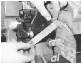
12.3 Removing the alternator heat shield
4 Disconnect the heater hose from the water pump.
5 Drain the engine oil and remove the filter and oil cooler where applicable.
6 Jam the flywheel starter ring gear to prevent the crankshaft turning and unscrew the crankshaft pulley bolt. Remove the pulley.
7 Unbolt and remove the timing belt cover (4 bolts) (see illustration). Note that the cover is in two halves on later models.
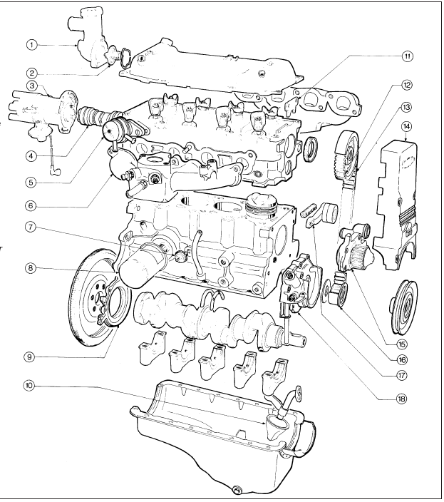
12.7 Exploded view of the engine
1 Thermostat housing
2 Thermostat
3 Distributor
4 Camshaft
5 Fuel pump
6 Inlet manifold
7 Oil pressure switch
8 Oil filter
9 Oil seal retainer
10 Oil pump pick-up tube and strainer
11 Camshaft thrust plate
12 Camshaft belt sprocket
13 Timing belt
14 Timing belt cover (one-piece type)
15 Water pump
16 Crankshaft belt sprocket
17 Timing belt tensioner
18 Oil pump
8 Slacken the two bolts on the timing belt tensioner, lever the tensioner against its spring pressure where applicable and tighten the bolts to lock it in position.
9 With the belt now slack, note its running direction and mark the mating belt and sprocket teeth with a spot of quick-drying paint. This is not necessary if the belt is being renewed.
10 Disconnect the spark plug leads and, where applicable, remove the distributor cap complete with HT leads (if not already done).
11 Unscrew and remove the spark plugs.
12 Disconnect the crankcase ventilation hose from its connector on the crankcase.
13 Remove the rocker cover (see illustration).
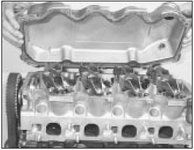
12.13 Remove the rocker cover
14 Unscrew the cylinder head bolts in the sequence shown in illustration 7.18 and discard them. New bolts must be used at reassembly.
15 Remove the cylinder head complete with manifolds.
16 Turn the engine on its side. Do not invert it as sludge in the sump may enter the oilways.
Remove the sump bolts, withdraw the sump and peel off the gaskets and sealing strips.
17 Remove the bolts from the clutch pressure plate in a progressive manner until the pressure of the assembly is relieved and then remove the cover, taking care not to allow the friction plate to fall to the floor.
18 Unbolt and remove the flywheel. The bolt holes are offset so it will only fit one way.
19 Remove the engine adapter plate.
20 Unbolt and remove the crankshaft rear oil seal retainer.
21 Unbolt and remove the timing belt tensioner and take out the coil spring. (This spring is not used on all models).
22 Unbolt and remove the water pump.
23 Remove the belt sprocket from the crankshaft using the hands or if tight, a twolegged puller. Take off the thrustwasher.
24 Unbolt the oil pump and pick-up tube and remove them as an assembly.
25 Unscrew and remove the oil pressure switch (see illustration).
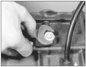
12.25 Unscrew the oil pressure switch
26 Turn the crankshaft so that all the pistons are half-way down the bores, and feel if a wear ridge exists at the top of the bores. If so, scrape the ridge away, taking care not to damage the bores.
27 Inspect the big-end and main bearing caps for markings. The main bearings should be marked 1 to 5 with a directional arrow pointing to the timing belt end. The big-end caps and connecting rods should have adjacent matching numbers. Number 1 is at the timing belt end of the engine. Make your own marks if necessary.
28 Unscrew the bolts from the first big-end cap and remove the cap. The cap is located on two roll pins, so if the cap requires tapping off make sure that it is not tapped in a sideways direction.
29 Retain the bearing shell with the cap if the shell is to be used again.
30 Push the piston/connecting rod out of the top of the cylinder block, again retaining the bearing shell with the rod if the shell is to be used again.
31 Remove the remaining pistons/rods in a similar way.
32 Remove the main bearing caps, keeping the shells with their respective caps if the shells are to be used again. Lift out the crankshaft.
33 Take out the bearing shells from the crankcase, noting the semi-circular thrustwashers on either side of the centre bearing. Keep the shells identified as to position in the crankcase if they are to be used again.
34 Prise down the spring arms of the crankcase ventilation baffle and remove it from inside the crankcase just below the ventilation hose connection.
35 The engine is now completely dismantled and each component should be examined as described in Section 13 before reassembling.
See also:
Ford Sierra Service Manual
...
Wheel sensor (ABS) - removal and refitting
Note: A new O-ring must be used when
refitting a sensor.
Front wheel sensor
1 Apply the handbrake, loosen the relevant
front roadwheel nuts, then jack up the front of
the vehicle and support on a ...
Headlining - removal and refitting
Saloon, Hatchback and Estate
models
1 On Saloons, remove the rear seat back.
2 Loosen the upper screws of all the pillar
trim panels touching the headlining.
3 Prise off the covers and remove the ...
