Steering gear - removal, overhaul and refitting
Removal
Note: New tie-rod balljoint split-pins must be
used on refitting.
1 Set the front roadwheels in the straightahead position.
2 Raise the front of the vehicle and fit stands (see “Jacking and Vehicle Support”). Remove the front roadwheels.
3 Working under the bonnet, remove the pinch-bolt from the coupling at the base of the steering column shaft.
4 Extract the split pins from the tie-rod balljoint taper pin nuts, unscrew the nuts and remove them.
5 Separate the balljoints from the steering arms using a suitable separator tool.
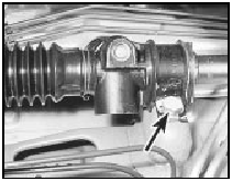
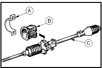
6 Flatten the locktabs on the steering gear securing bolts and unscrew and remove the bolts. Withdraw the steering gear downwards to separate the coupling from the steering shaft and then take it out from under the front wing (see illustrations).

26.6a Steering gear-to-bulkhead mounting retaining bolt and locktab (arrowed)

26.6b Steering gear mounting details
A Clamp
B Bush
C Steering gear
Overhaul 7 Examine the steering gear assembly for signs of wear or damage, and check that the rack moves freely throughout the full length of its travel, with no signs of roughness or excessive free play between the steering gear pinion and rack. It is possible to overhaul the steering gear assembly housing components, but this task should be entrusted to a Ford dealer. It is likely to be cheaper to obtain an exchange reconditioned steering gear assembly (which will be supplied complete with tie-rods) than to overhaul a worn or damaged assembly. The only components which can be renewed easily by the home mechanic are the steering gear bellows, and the tie-rod outer balljoints. Renewal procedures for the bellows and tie-rod outer balljoints are given in Sections 20 and 21 respectively.
Refitting
8 If a new steering gear assembly is being
installed, the tie-rods balljoints may have to
be removed from the original unit and
screwed onto the new tie-rods to
approximately the same setting. If a note was
not made of the position of the original tie-rod
balljoints on their rods, inspection of the
threads will probably indicate their original
location. In any event it is important that the
new balljoints are screwed on an equal
amount at this stage.
9 Make sure that the steering gear is centred.
Do this by turning the pinion shaft to full lock in one direction and then count the number of turns required to rotate it to the opposite lock.
Now turn the splined pinion shaft through half the number of turns just counted.
10 Check that the roadwheels and the steering wheel are in the straight-ahead attitude, offer up the steering gear and connect the shaft coupling without inserting the pinch-bolt.
11 Bolt up the gear housing and lock the bolts with their lockplate tabs.
12 Reconnect the tie-rod balljoints to the steering arms. Tighten the securing nuts to the specified torque setting and fit new split pins to secure.
13 Tighten the coupling pinch-bolt to the specified torque. Refit the roadwheels and lower the vehicle to the floor.
14 If the tie-rods were disturbed or if a new assembly was installed, check and adjust the wheel alignment, as described in Section 27.
See also:
Rear disc caliper - removal, overhaul and refitting
Note: Complete dismantling of the rear caliper
should not be attempted unless Ford spring
compressor (tool No 12-007) is available, or
unless the problems likely to arise in the
absence of the too ...
Windscreen and fixed window glass - removal and refitting
Windscreen
Note: The average DIY mechanic is advised to
leave windscreen removal and refitting to an
expert. For the owner who insists on doing it
himself, the following paragraphs are given.
Rem ...
Rear parcel shelf - removal and refitting
Removal
1 Open the tailgate fully and disengage the
parcel shelf lifting strap loops from the tailgate
retaining knobs.
2 Lift out the parcel shelf pivot pins from their
notches in the support br ...
