
Electric cooling fan - removal and refitting
CVH models
1 Disconnect the battery negative lead.
Unclip the wiring connector from the fan motor then unscrew the retaining nuts and washers. Withdraw the fan shroud and cooling fan assembly (see illustration).
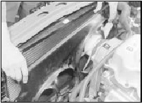
13.1 Withdrawing the fan shroud and cooling fan assembly
2 To remove the fan blades, prise the securing clip from the end of the motor shaft (see illustration).
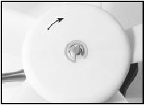
13.2 Fan blade securing clip and direction of rotation arrow
3 The motor can be separated from the fan shroud by unscrewing the three securing nuts and bolts.
4 Where two cooling fans are fitted, both fans are secured to the fan shroud in the same manner.
5 Refitting is a reversal of removal, but when refitting the fan blades, ensure that the direction of rotation arrow faces away from the motor, towards the radiator.
DOHC models
6 Disconnect the battery negative lead.
7 To provide additional clearance when removing the cooling fan shroud assembly (which is removed from below the vehicle), apply the handbrake, then jack up the front of the vehicle and support it securely on axle stands (see “Jacking and Vehicle Support”).
8 Disconnect the wiring plug(s) from the motor(s), and where applicable, unclip the wiring from the fan shroud.
9 Unclip the expansion tank hose from the fan shroud.
10 Unscrew the two nuts securing the fan shroud to the top of the radiator, then tilt the top of the shroud away from the radiator, and lift the shroud to release the lower securing clips. Withdraw the assembly from below the vehicle.
11 To remove the fan blades, prise the securing clip from the end of the motor shaft.
12 The motor can be separated from the fan shroud by unscrewing the three securing nuts and bolts.
13 Where two cooling fans are fitted, both are secured to the shroud in the same manner.
14 Refitting is a reversal of removal, but when fitting the fan blades, ensure that the drive dog on the motor shaft engages with the slot in the rear of the fan blades.
Cooling fan switch - removal and refitting
On CVH models, the cooling fan switch is located on the right-hand side of the thermostat housing (see illustration). On DOHC models, the switch is located in the end of the thermostat housing.
Removal and refitting of the switch is as described for the temperature gauge sender.
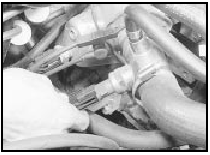
14.1 Disconnecting the wiring plug from the cooling fan switch
See also:
Handbrake - adjustment
1 Adjustment of the handbrake is normally
automatic by means of the self-adjusting
mechanism working on the rear brake shoes.
2 However, due to cable stretch, occasional
inspection of the handbrak ...
Seat belts - removal and refitting
Front belt - 3-door models
Note: Note the fitted sequence of any plates,
washers and spacers when unbolting the seat
belt anchors.
Removal
1 Slide the belt stalk cover upwards to
expose the anch ...
Crankcase ventilation system check (Every 12 000 miles (20 000 km) or 12
months)
1 Inspect the crankcase ventilation system
for blockage or damage. A blocked hose can
cause a build-up of crankcase pressure,
which in turn can cause oil leaks (see
illustration).
35.1 Loosenin ...
