Starter motor - testing in the vehicle
1 If the starter motor fails to operate first check the condition of the battery.
2 Check the security and condition of all relevant wiring.
Solenoid check
3 Disconnect the battery negative lead and all
leads from the solenoid.
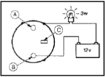
4 Connect a 3 watt test lamp and a 12 volt battery between the starter terminal on the solenoid and the solenoid body as shown (see illustration). The testlamp should light. If not, there is an open circuit in the solenoid windings.

9.4 Starter motor solenoid winding test circuit
A Battery terminal
B Motor terminal
C Spade terminal
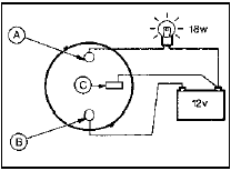
5 Now connect an 18 watt testlamp between both solenoid terminals (see illustration),

9.5 Starter motor solenoid continuity test circuit
A Battery terminal
B Motor terminal
C Spade terminal
then energise the solenoid with a further lead to the spade terminal. The solenoid should be heard to operate and the testlamp should light. Reconnect the solenoid wires.
On load voltage check
6 Connect a voltmeter across the battery
terminals, then disconnect the low tension
lead from the coil positive terminal and
operate the starter by turning the ignition
switch. Note the reading on the voltmeter
which should not be less than 10.5 volts.
7 Now connect the voltmeter between the starter motor terminal on the solenoid and the starter motor body. With the coil low tension lead still disconnected operate the starter and check that the recorded voltage is not more than 1 volt lower than that noted in paragraph 6. If the voltage drop is more than 1 volt a fault exists in the wiring from the battery to the starter.
8 Connect the voltmeter between the battery positive terminal and the terminal on the starter motor. With the coil low tension lead disconnected operate the starter for two or three seconds. Battery voltage should be indicated initially, then dropping to less than 1 volt. If the reading is more than 1 volt, there is a high resistance in the wiring from the battery to the starter and the check in paragraph 9 should be made. If the reading is less than 1 volt proceed to paragraph 10.
9 Connect the voltmeter between the two main solenoid terminals and operate the starter for two or three seconds. Battery voltage should be indicated initially, then dropping to less than 0.5 volt. If the reading is more than 0.5 volt, the ignition switch and connections may be faulty.
10 Connect the voltmeter between the battery negative terminal and the starter motor body, and operate the starter for two or three seconds. A reading of less than 0.5 volt should be recorded. If the reading is more than 0.5 volt, there is a fault in the earth circuit, and the earth connections to the battery and body should be checked.
See also:
Glove compartment - removal and refitting
Pre-1986 models
Removal
1 Open the glovebox lid and extract the
screws which hold the glovebox to the facia.
2 Remove the latch (two screws).
3 Remove the single screw inside the top of
the glov ...
Key to wiring diagrams
Key to wiring diagrams
Key to wiring diagrams ...
Engine oil cooler - removal and refitting
Note: Suitable sealant will be required on
refitting - see text.
Removal
1 Remove the engine oil filter (Chapter 1).
2 Note the angle at which the coolant hoses
are set, then disconnect the hoses ...
