Steering column adjuster - dismantling and reassembly
Note: A new adjuster locknut and washer must be used on reassembly.
Dismantling
1 To dismantle the adjuster assembly,
proceed as follows.
2 Remove the locknut and washer securing the adjuster through-bolt (see illustration).
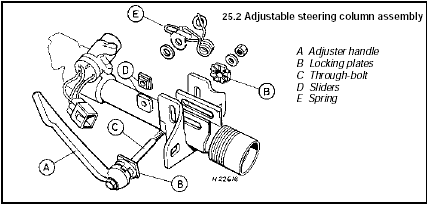
25.2 Adjustable steering column assembly
A Adjuster handle
B Locking plates
C Through-bolt
D Sliders
E Spring
3 Remove the through-bolt, adjuster handle, locking plates, sliders and washers, then unclip the spring assembly.
Reassembly
4 Reassemble the components as follows.
5 Refit the spring to the adjuster assembly bracket.
6 Align the washers, sliders and locking plates, ensuring that the handle locking plate is fitted so that the cut-out and Ford logo are positioned as shown (see illustration).
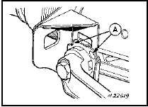
25.6 Cut-out and Ford logo (A) must be positioned as shown when reassembling
adjustable steering column
7 Coat the through-bolt threads with a suitable thread-locking compound, then refit the through-bolt and the adjuster handle, ensuring that all components are engaged.
8 Position the handle in the locked position, and secure the through-bolt with a new locknut and washer.
See also:
Engine oil and filter renewal (Every 6000 miles (10 000 km) or 6 months)
1 Frequent oil and filter changes are the most
important preventative maintenance
procedures which can be undertaken by the
DIY owner. As engine oil ages, it becomes
diluted and contaminated, whic ...
Hydraulic unit accumulator (ABS) - removal and refitting
Note: A new O-ring must be used between
the accumulator and the hydraulic unit on
refitting.
Caution: Refer to the
precautions in Section 1.
Removal
1 Disconnect the battery negative lead.
2 De ...
Suspension and steering check (Every 6000 miles or 6 months)
Front suspension and steering
check
1 Raise the front of the vehicle, and securely
support it on axle stands (see “Jacking and
Vehicle Support”).
2 Visually inspect the balljoint dust covers
and ...
