Cylinder head - removal and refitting
Removal
Note: On HCS engines, cylinder head bolts
may be used a total of three times (including
initial fit) and must be suitably marked to
indicate each removal operation. A new
cylinder head gasket must be used on refitting.
1 If the engine is in the car carry out the preliminary operations described in paragraphs 2 to 16.
2 Disconnect the battery negative terminal.
3 Remove the air cleaner (Chapter 4, Part A).
4 Drain the cooling system (Chapter 1).
5 Disconnect the hoses from the thermostat housing.
6 Disconnect the heater hose from the upper connection on the automatic choke housing, or inlet manifold as applicable (see illustrations).
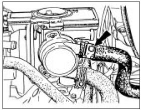
4.6a Heater hose connection on choke housing
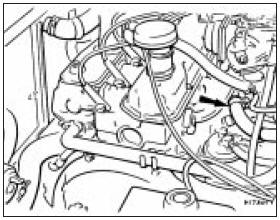
4.6b Heater hose connection at inlet manifold
7 Release the throttle cable from the carburettor operating lever by moving the spring clip and removing the bracket fixing bolt (see illustration).
4.7 Throttle cable disconnection points
8 On manual choke models disconnect the choke cable from the linkage lever and support bracket.
9 Disconnect the fuel and vacuum pipes from the carburettor.
10 Disconnect the breather hose from the inlet manifold.
11 On vehicles with servo-assisted brakes, disconnect the vacuum hose from the inlet manifold.
12 Disconnect the HT leads from the spark plugs.
13 Disconnect the electrical leads from the temperature sender unit, the anti-run-on solenoid valve at the carburettor, and the radiator fan thermal switch.
14 Unbolt and remove the hot air box from the exhaust manifold.
15 Disconnect the exhaust downpipe from the manifold by unbolting the connecting flanges. Support the exhaust system at the front end.
16 Remove the oil filler cap with breather hose.
17 Extract the four screws and remove the rocker cover.
18 Unscrew and remove the four fixing bolts and lift away the rocker shaft assembly from the cylinder head.
19 Withdraw the pushrods, keeping them in their originally fitted sequence. A simple way to do this is to punch holes in a piece of card and number them 1 to 8 from the thermostat housing end of the cylinder head.
20 Remove the spark plugs.
21 Unscrew the cylinder head bolts progressively in the reverse order to that given for tightening (see illustration 4.27). Remove the cylinder head.
22 To dismantle the cylinder head, refer to Section 13.
Refitting
23 Before refitting the cylinder head, remove
every particle of carbon, old gasket and dirt
from the mating surfaces of the cylinder head
and block. Do not let the removed material
drop into the cylinder bores or waterways, if it
does, remove it. Normally, when a cylinder
head is removed, the head is decarbonised
and the valves ground in as described in
Section 14 to remove all trace of carbon.
Clean the threads of the cylinder head bolts and mop out oil from the bolt holes in the cylinder block. In extreme cases, screwing a bolt into an oil-filled hole can cause the block to fracture due to hydraulic pressure.
24 If there is any doubt about the condition of the inlet or exhaust gaskets, unbolt the manifolds and fit new ones to perfectly clean mating surfaces.
25 Locate a new cylinder head gasket on the cylinder block, making quite sure that the bolt holes, coolant passages and lubrication holes are correctly aligned.
26 Lower the cylinder head carefully into position on the block.
27 Screw in all the bolts finger tight and then tighten them in the stages given (see Specifications), and in the sequence shown to the specified torque (see illustration). Note that on all except HCS engines with M11 neckedshank (a reduced diameter section between the bolt head and the threaded portion) cylinder head bolts there are four tightening stages. On HCS engines with M11 necked-shank cylinder head bolts there are three tightening stages.
4.27 Cylinder head bolt tightening sequence
28 Refit the pushrods in their original order.
29 Lower the rocker shaft assembly into position, making sure that the rocker adjusting screws engage in the sockets at the ends of the pushrods.
30 Screw in the rocker pedestal bolts finger tight. At this stage, some of the rocker arms will be applying pressure to the ends of the valve stems and some of the rocker pedestals will not be in contact with the cylinder head.
The pedestals will be pulled down however when the bolts are tightened to the specified torque, which should now be done.
31 Adjust the valve clearances as described in Chapter 1.
32 Refit the rocker cover, using a new gasket. Do not exceed the specified torque for the securing screws; this may result in oil leaks at the rocker cover/cylinder head mating face.
33 Fit the oil filler cap and breather hose and the spark plugs. Tighten these to the specified torque. They are of tapered seat type, no sealing washers being used.
34 Connect the exhaust downpipe and fit the hot air box.
35 Reconnect all electrical leads, vacuum and coolant hoses.
36 Reconnect the throttle and choke cables as described in Chapter 4, Part A.
37 Refit the air cleaner as described in Chapter 4, Part A and fill the cooling system as described in Chapter 1.
38 Reconnect the battery negative terminal.
See also:
Major operations requiring engine removal
The following work can only be carried out
after removal of the engine from the car:
a) Crankshaft main bearings - renewal.
b) Crankshaft - removal and refitting.
c) Flywheel - removal and refitti ...
Heater only system (if equipped)
Fan speed control
Controls the volume of air circulated
in the vehicle.
Temperature control knob
Controls the temperature of the
airflow inside the vehicle. On
heater-only systems, t ...
Steering column - removal, overhaul and refitting
Removal
1 Disconnect the battery negative terminal.
2 Turn the ignition key and rotate the steering
wheel to bring the front roadwheels to the
straight-ahead position.
3 Working within the engine ...
