Ignition system electronic modules - removal and refitting
Amplifier module - electronic
breakerless system
Removal
1 The amplifier module is located on the side
of the distributor (see illustration).
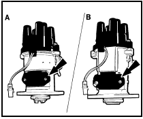
6.1 Electronic amplifier module locations
A Early type Bosch distributor B Early type Lucas distributor
2 If necessary, to improve access remove the distributor as described in Section 5.
3 Remove the two securing screws, and withdraw the module from the side of the distributor (see illustrations).
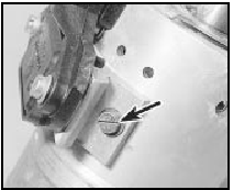
6.3a Electronic amplifier securing screw (arrowed) - later type Bosch
distributor
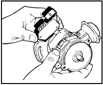
6.3b Removing the electronic amplifier module - later type Lucas distributor
Refitting 4 Start refitting by cleaning all traces of old heat sink compound from the distributor body.
5 Apply fresh heat sink compound (supplied with new amplifier modules) to the back of the amplifier before fitting.
6 Refit the module and tighten the securing screws.
7 Where applicable, refit the distributor as described in Section 5.
RS Turbo engines (ESC II)
Electronic Spark Control (ESC II)
module
Removal
8 Disconnect the battery negative terminal.
9 Remove the heater plenum chamber top
cover rubber seal,
10 Release the five retaining clips and lift off
the plenum chamber top cover (see
illustrations).
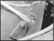
6.10a Release the retaining clips . . .
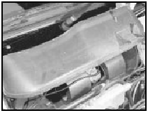
6.10b . . . and remove the plenum chamber top cover
11 Undo the two nuts securing the heater fan motor assembly to the bulkhead. Lift the unit off the studs and place it on the engine. Avoid straining the wiring (see illustration).
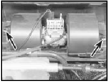
6.11 Undo the fan motor retaining nuts (arrowed)
12 Unclip and detach the wiring multi-plug from the spark control module (see illustration).
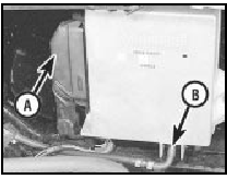
6.12 Spark control module wiring multiplug (A) and vacuum hose (B)
13 Undo the retaining screws and remove the module from the bulkhead. Detach the module vacuum hose.
Refitting
14 Refitting is the reverse sequence to
removal. Take care not to trap the motor
wiring when refitting the fan motor assembly,
and ensure that it is engaged in the slot
provided in the housing.
1.1 and 1.3 litre HCS engines
(DIS/ESC)
Warning: The DIS system carries
much higher voltages than
conventional systems, and
adequate precautions must be
taken to avoid personal injury. Refer to the
“Safety first!” Section at the beginning of
this manual before proceeding, and
always disconnect the battery negative
lead before working on the system
ESC module
Removal
15 The module is located on the front lefthand
inner wing panel.
16 Disconnect the battery negative lead.
17 Disconnect the vacuum hose from the module (see illustration).
6.17 Disconnecting the vacuum hose from the ESC module
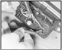
18 Unscrew the central securing screw, and disconnect the wiring plug (see illustration).
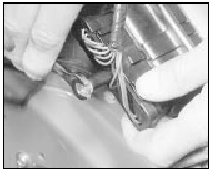
6.18 Unscrewing the ESC module wiring plug securing screw
19 Remove the two screws securing the module to the wing panel, and withdraw the module (see illustration).
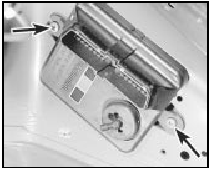
6.19 ESC module securing screws (arrowed)
Refitting 20 Refitting is a reversal of removal.
Fuel trap
21 A fuel trap is fitted in the vacuum line
between the inlet manifold and the ESC
module.
22 When refitting the fuel trap, the side marked “DIST” must face the ESC module, and the side marked “CARB” must face the inlet manifold.
1.4 litre fuel injection engines
(EEC IV)
TFI IV module
Removal
23 The TFI IV module is located on the front
left-hand inner wing panel.
24 Disconnect the battery negative lead.
25 Depress the locking tabs and disconnect the module wiring plug.
26 Remove the retaining screws, and withdraw the module.
Refitting
27 Refitting is a reversal of removal.
EEC IV module
28 Refer to Chapter 4, Part C.
1.6 litre Electronic Fuel Injection
engines (EEC IV)
E-DIS 4 module
Refitting
29 The module is located on the front lefthand
inner wing panel in the engine
compartment (see illustration).
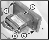
6.29 E-DIS-4 module location
A Module
B Wiring plug
C Securing
screws
30 Disconnect the battery negative lead.
31 Disconnect the module wiring plug. Do not pull on the wiring.
32 Remove the two securing screws and withdraw the module.
Refitting
33 Refitting is a reversal of removal.
EEC IV module
34 Refer to Chapter 4, Part D.
See also:
Hydraulic pipes and hoses - renewal
Note: Before starting work, refer to the
warning at the beginning of Section 3
concerning the dangers of hydraulic fluid.
1 Always disconnect a flexible hose by
prising out the spring anchor clip ...
Air cleaner - removal and refitting
The procedure is similar to that described in
Part B of this Chapter for models with
mechanical fuel injection. ...
Driveshaft check (Every 12 000 miles or 12 months)
1 Carry out a thorough inspection of the
driveshafts and joints as follows.
2 Jack up the front of the car and support it
securely on axle stands (see “Jacking and
Vehicle Support”).
3 Slowly rot ...
