Modulator drivebelt (antilock braking system) - removal and refitting
Note: Whenever an ABS modulator adjuster bolt is slackened or removed, the bolt threads should be lightly coated with grease to prevent the possibility of bolt seizure. Take care not to contaminate surrounding components when applying the grease.
Right-hand side
Removal
Note: A new driveshaft snap-ring and a new
tie-rod balljoint split-pin will be required on
refitting.
1 Jack up the front of the car, support it on stands (see “Jacking and Vehicle Support”) and remove the roadwheel.
2 Remove the belt break switch from the drivebelt cover by pushing it upward and carefully levering out the bottom edge. Pull the switch down, withdraw the switch arm from the opening in the cover and place the switch to one side (see illustration).
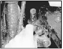
20.2 Removing the belt break switch from the modulator drivebelt cover
3 Undo the two drivebelt cover retaining nuts and washers, and on later models (1987-on), the retaining bolt (see illustrations).
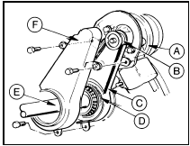
20.3a Modulator and drivebelt details
A Modulator
B Sprocket
C Drivebelt
D Constant
velocity joint
E Driveshaft
F Drivebelt cover
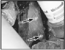
20.3b Drivebelt cover retaining nuts (arrowed) - models up to 1987
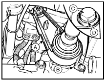
20.3c Right-hand side ABS modulator drivebelt cover - 1987-on models
A Guard
B Support bracket
C Bolt
D Washer
4 Withdraw the cover from the studs and remove it by moving it upwards to clear the oil filter.
5 Slacken the modulator adjuster bolt, move the modulator to relieve the tension on the drivebelt then slip the belt off the modulator sprocket (see illustration).
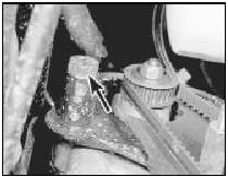
20.5 Modulator adjuster bolt (arrowed)
6 Extract the split pin, undo the retaining nut and separate the tie-rod balljoint from the steering arm using a suitable balljoint separator tool.
7 Disconnect the front suspension lower arm balljoint from the hub carrier by removing the nut and pinch-bolt (see illustration). Note that the pinch-bolt is of the socket-headed (Torx) type and a special key or socket bit will be required for this purpose. These are readily available from most accessory shops.
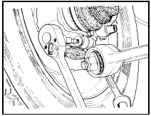
20.7 Removing suspension lower arm balljoint pinch-bolt
8 Place a suitable container beneath the driveshaft inner constant velocity joint.
9 Insert a lever between the inner constant velocity joint and the transmission housing.
Firmly strike the lever to release the constant velocity joint from the differential.
10 Pull the driveshaft out of the transmission and slip the modulator drivebelt off the joint.
Allow the transmission oil to drain into the container.
11 With the driveshaft disconnected, suspend it in such a way so as not to adopt an angle of more than 45° from the outer constant velocity joint.
Refitting
12 Before refitting the drivebelt, renew the
snap-ring fitted to the splines of the inner
constant velocity joint.
13 Ensure that the modulator sprocket and constant velocity joint splines are clean and dry then slip the drivebelt over the joint.
14 Engage the joint splines with the differential and firmly push the hub carrier inwards to force the joint home.
15 Reconnect the lower arm balljoint to the hub carrier and insert the Torx bolt with its head to the rear. Refit the nut and tighten to the specified torque.
16 Reconnect the tie-rod balljoint to the steering arm, fit and tighten the nut to the specified torque and secure with a new split pin.
17 Slip the drivebelt over the modulator sprocket ensuring that it sits squarely in the sprocket teeth.
18 Move the modulator as necessary to tension the belt so that the belt deflection, under light finger pressure, is 5.0 mm. Check this using a ruler at a point midway between the two sprockets (see illustration).
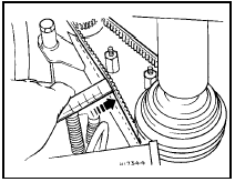
20.18 Using a ruler to check right-hand drivebelt adjustment
19 With the belt tensioned correctly, tighten the modulator adjuster bolt. Before tightening, the adjuster bolt threads should be coated with grease - refer to the note at the beginning of this Section.
20 Refit the drivebelt cover and secure with the two nuts and washers, and the bolt (where applicable).
21 Engage the belt break switch arm upwards through the opening in the drivebelt cover then locate the switch in position. Pull the switch downward to secure.
22 Refit the roadwheel and lower the car to the ground.
23 Top-up the transmission oil as described in Chapter 1.
Left-hand side
24 The procedure is the same as for the
right-hand side but note the following
differences.
25 Remove the engine splash shield from the inner wheel arch.
26 When removing the drivebelt cover note that it is secured by three bolts, two at the top and one at the bottom (see illustration).
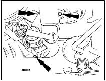
20.26 Left-hand drivebelt cover retaining bolt locations (arrowed)
27 To move the modulator for adjustment of the belt tension, use a suitable length of wood inserted through the steering tie-rod aperture in the inner wheel arch, to push on the modulator as necessary.
See also:
Pistons and connecting rods - removal and refitting
1.8 litre (R2A type)
Removal
1 With the engine removed from the vehicle,
remove the sump and the cylinder head.
2 Check the big-end caps for identification
marks and if necessary use a centre-pun ...
Fuel injectors - removal and refitting
Caution: Refer to the
precautions in Section 1 before
proceeding.
Note: A tachometer and an exhaust gas
analyser will be required to check the idle
mixture on completion. New seals and
retaining ...
General description
The cooling system is of the pressurised
pump-assisted thermo-syphon type. The
system consists of the radiator, water pump,
thermostat, electric cooling fan, expansion
tank and associated hoses.
...
