
Diagram 3a: 1986-on Ancilliary circuits all models
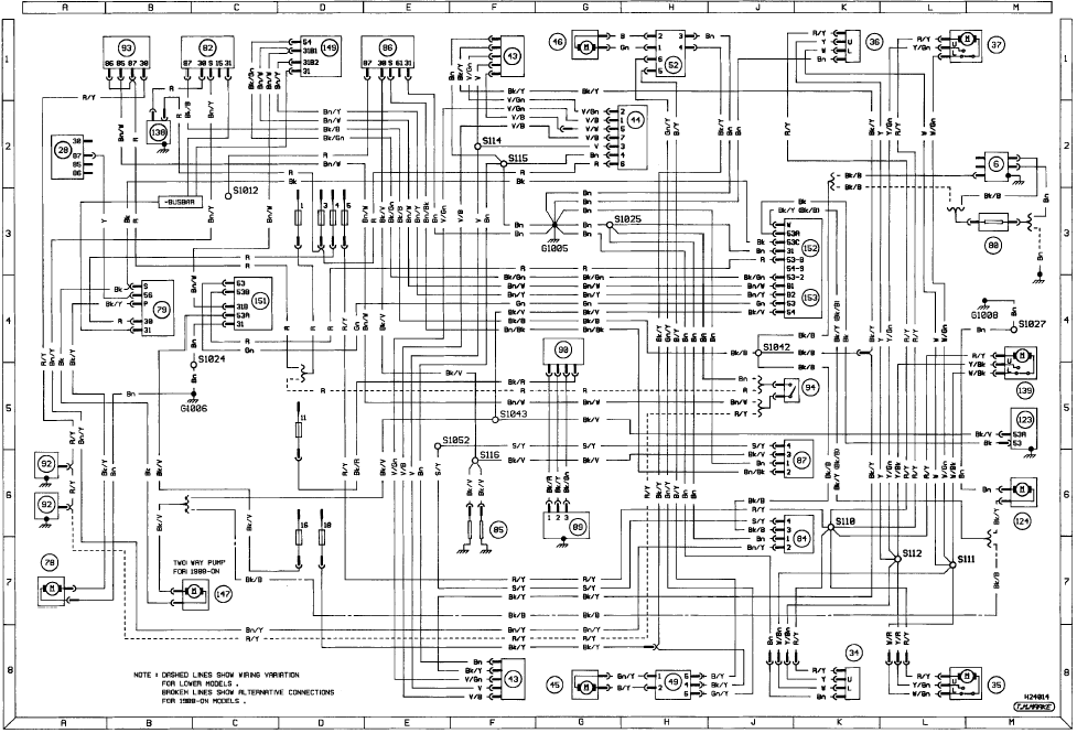
Diagram 3a: 1986-on Ancilliary circuits all models
See also:
Door trim panel - removal and refitting
Pre-1986 models
Removal
1 On Ghia versions only, remove the panel
capping by carefully prising out the retaining
clips using a forked tool. This can easily be
made from a piece of scrap metal.
2 ...
Alternator - removal and refitting
Note: Refer to the precautions at the end of
Section 1 before proceeding.
Removal
1 The operations are similar for all makes of
alternator.
2 Disconnect the battery negative terminal,
then disco ...
General description
The braking system is of the dual circuit
hydraulic type with disc brakes at the front
and drum brakes at the rear. A diagonally split
dual circuit hydraulic system is employed in
which each circu ...
