Diagram 4: 1983-on K-Jetronic fuel injection
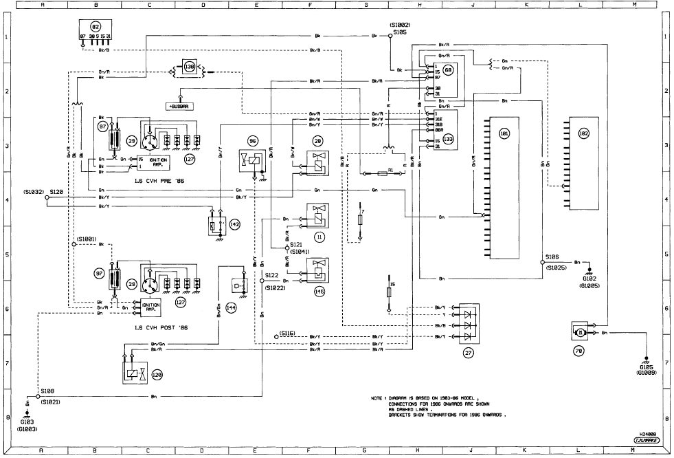
Diagram 4: 1983-on K-Jetronic fuel injection For starting and charging
circuits see Diagram 1
See also:
Specifications
Battery
Type . . . . . . . . . . . . . . . . . . . . . . . . . . . . . . . . . . . . . .
. . . . . . . . . . . . . . 12 volt lead-acid, 35 to 52 Ah depending on model
Charge condition:
Poor . . . ...
Rear shock absorber (Saloon and Estate models) - removal,
testing and refitting
Removal
1 Slacken the roadwheel bolts, raise the rear
of the vehicle, support it on stands (see
“Jacking and Vehicle Support”) and remove
the roadwheel.
2 Support the suspension lower arm with a
...
Getting roadside assistance
To fully assist you should you have a vehicle concern, Ford Motor
Company offers a complimentary roadside assistance program. This
program is separate from the New Vehicle Limited Warranty. The serv ...
