Cylinder head - dismantling and reassembly
Note: A valve spring compressor will be required during this procedure. New valve stem oil seals should be used on reassembly.
Dismantling
1 With the cylinder head removed, remove
the camshaft.
2 Using a valve spring compressor, compress one of the valve springs until the split collets can be removed from the groove in the valve stem. Release the compressor and remove the cap and spring, identifying them for location. If the cap is difficult to release, do not continue to tighten the compressor, but gently tap the top of the tool with a hammer.
Always make sure that the compressor is firmly located on the valve head and the cap.
Withdraw the valve (see illustrations).
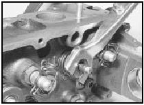
22.2a Compressing a valve spring
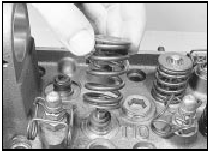
22.2b Removing a valve spring and cap
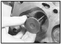
22.2c Removing a valve
3 Repeat the procedure given in paragraph 2 for the remaining valves, keeping all components identified for location so that they can be refitted in their original positions.
4 Prise the valve stem oil seals from the tops of the valve guides (see illustration).
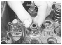
22.4 Removing a valve stem oil seal
5 Unscrew the cam follower ball-pins from the cylinder head, keeping them identified for location.
Reassembly
6 Commence reassembly by refitting the cam
follower ball-pins to their original locations,
where applicable.
7 Lubricate the valve stems and guides with SAE 80/90 hypoid oil, then insert the valves into their original guides.
8 Wrap a thin layer of adhesive tape over the collet groove of each valve, then smear the new oil seals with a little SAE 80/90 hypoid oil and slide them down the valve stems onto the guides. If necessary use a suitable metal tube to press the oil seals into the guides. Remove the adhesive tape.
9 Working on each valve in turn, fit the valve spring and cap, then compress the spring using the valve spring compressor and fit the split collets to the groove in the valve stem.
Release the compressor and tap the end of the valve stem with a soft-faced mallet to settle the components. If the original components are being refitted, ensure that they are refitted in their original locations.
10 Refit the camshaft.
See also:
Cylinder head - removal and refitting (engine removed)
Note: The cylinder head bolts must always be
renewed after slackening, and a new cylinder
head gasket and camshaft cover gasket must
be used on refitting. If the engine has recently
run, the cylin ...
Water pump - removal and refitting
OHV engines
Note: A new gasket and suitable jointing
compound must be used on refitting.
Removal
1 Drain the cooling system as described in
Chapter 1.
2 Slacken the three water pump pulley
reta ...
Folding roof (Cabriolet models) - removal and refitting
Removal
1 Remove the rear side, wheel arch and roof
stowage compartment trim panels.
2 Disconnect the heated rear window wiring
and pull it from the weatherstrip.
3 Release the roof front locking ...
