Sump - removal and refitting
Warning: A new sump gasket will be required on refitting, and suitable sealing compound will be required to coat the sump and cylinder block mating faces.
Shims may be required when mating the engine and gearbox/transmission - see text.
Removal
1 Sump removal and refitting is far easier if
the engine is removed from the vehicle - if so,
proceed to paragraph 9. However, if the
engine is in the vehicle, proceed as follows.
2 Remove the gearbox and clutch, or automatic transmission, as applicable.
3 Remove the flywheel/driveplate and the engine adapter plate.
4 Drain the engine oil into a container.
5 Ensure that the steering wheel is positioned in the straight-ahead position, then remove the clamp bolt from the lower steering column clamp, swivel the plate to one side, and disconnect the lower steering column from the lower flexible coupling.
6 Attach a suitable hoist to the engine lifting brackets located at the front and rear of the cylinder head, and carefully take the weight of the engine.
7 Detach the brake lines from the front suspension crossmember.
8 Support the crossmember with a jack, then loosen the bolts securing the crossmember to the underbody. Remove the bolts, and carefully lower the crossmember sufficiently to allow the sump to be removed.
9 If the engine has been removed, it is preferable to keep it upright until the sump has been removed, to prevent sludge in the sump from entering the engine internals.
10 Unscrew the sump securing nuts and bolts, and withdraw the sump from the engine. If the sump is stuck, gently tap it sideways to free it (the sump will not move far sideways, as it locates on studs in the cylinder block). Do not prise between the mating faces of the sump and block. Recover the gasket.
11 Thoroughly clean the mating faces of the cylinder block and sump.
Refitting
12 Commence refitting by locating a new
gasket in the grooves in the sump.
13 Apply a suitable sealing compound to the faces of the cylinder block and sump, at the points indicated (see illustration).
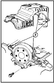
25.13 Apply sealing compound to the sump/cylinder block mating faces at the
points indicated (2)
Dimensions are for guidance only
14 Locate the sump on the cylinder block, then apply suitable thread-locking compound to the sump securing studs and bolts. Fit the securing nuts and bolts, but do not fully tighten them at this stage.
15 Align the sump so that its end faces and the cylinder block are flush. To do this, use a straight-edge. If the sump cannot be positioned so that the faces of the cylinder block and sump are flush, measure the difference in height using a feeler blade as shown (see illustration).

25.15 Measuring the clearance between the cylinder block and sump end faces
16 Tighten the sump securing nuts and bolts to the specified torque, then repeat the measurement made in paragraph 15. If the end faces of the sump and cylinder block are not flush, suitable shims (available from a Ford dealer) must be fitted between the sump and the gearbox/transmission to eliminate the clearance when mating the engine to the gearbox/transmission. Note that shims should be fitted at both sides of the sump, as required. Select suitable shims from those listed in the following table: Clearance measured Shims required 0 to 0.25 mm No shims required 0.25 to 0.29 mm 0.15 mm (silver) 0.30 to 0.44 mm 0.30 mm (light blue) 0.45 to 0.59 mm 0.45 mm (red) 0.60 to 0.75 mm 0.60 mm (black) 17 If the engine is in the vehicle, proceed as follows.
18 Reverse the procedure described in paragraphs 2 to 8, noting the following points.
19 Ensure that the roadwheels and the steering wheel are in the straight-ahead position before reconnecting the lower steering column to the intermediate shaft.
20 Fill the engine with the correct grade and quantity of oil.
21 Refit the engine adapter plate and the flywheel/driveplate.
22 Refit the gearbox or automatic transmission, ensuring that the required shims are fitted between the sump and the gearbox/transmission.
23 Tighten all fixings to the specified torque, where applicable.
See also:
Starter motor - testing in the vehicle
1 If the starter motor fails to operate first
check the condition of the battery.
2 Check the security and condition of all
relevant wiring.
Solenoid check
3 Disconnect the battery negative lead ...
Specifications
Fuel pump
Type . . . . . . . . . . . . . . . . . . . . . . . . . . . . . . . . . . . . . .
. . . . . . . . . . . . . . Mechanically-operated by eccentric on camshaft
Delivery pressure . . . . . . ...
Engine mountings - renewal
1 The engine mountings incorporate
hydraulic dampers and must be renewed if
excessive engine movement is evident.
2 Working in the engine compartment,
unscrew the central nuts securing the engine
...
