Thermostat - removal and refitting
1 Disconnect the battery negative lead.
2 Drain the cooling system.
3 Proceed as follows according to model:
SOHC models
4 Disconnect the radiator top hose and
expansion tank hose from the thermostat
housing situated at the front of the cylinder
head (see illustrations).
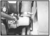
7.4a Radiator top hose connection at thermostat housing
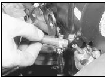
7.4b Disconnect the expansion tank hose from the thermostat housing
5 Unscrew the two securing bolts and remove the housing and gasket.
6 Using a screwdriver, prise the retaining clip from the housing, and extract the thermostat and sealing ring (see illustrations).
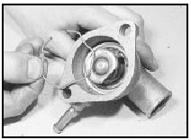
7.6a Prise out the retaining clip . . .
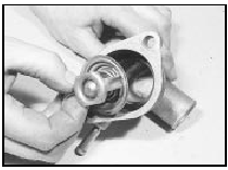
7.6b . . . and extract the thermostat . . .
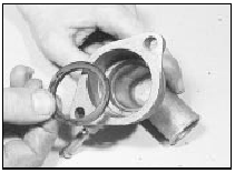
7.6c . . . and sealing ring
7 Refitting is a reversal of removal, bearing in mind the following points.
8 Clean the housing and the mating face of the cylinder head. Check the thermostat sealing ring for condition and renew it if necessary. Use a new gasket when refitting the housing.
9 The thermostat wax capsule must face into the cylinder head with the flow direction arrow facing forward (see illustration).
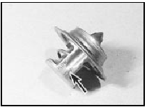
7.9 Thermostat flow direction markings (arrowed)
10 Refill the cooling system.
CVH models
11 Disconnect the wiring plug from the
cooling fan switch on the thermostat housing
situated at the front of the inlet manifold.
12 Disconnect the automatic choke hose, radiator top hose and expansion tank hose from the thermostat housing. Where applicable, take care not to strain the wiring which is routed around the housing. If necessary, disconnect the wiring connector (see illustrations).
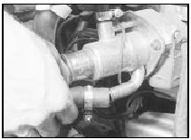
7.12a Disconnect the automatic choke hose . . .
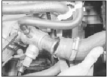
7.12b . . . the radiator top hose . . .
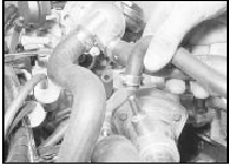
7.12c . . . and the expansion tank hose
13 Unscrew the three securing bolts and remove the housing and gasket (see illustration).
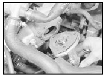
7.13 Removing the thermostat housing and gasket
14 Lift the thermostat from the housing, and carefully prise out the sealing ring.
15 Refitting is a reversal of removal, bearing in mind the following points.
16 Clean the housing and the mating face of the inlet manifold. Check the thermostat sealing ring for condition and renew it if necessary. Use a new gasket when refitting the housing.
17 Note that the thermostat wax capsule must face into the inlet manifold, with the flow direction arrow pointing forward, in line with the pressure relief valve in the housing (see illustration).
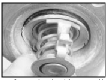
7.17 Correct orientation of thermostat with flow direction arrow pointing
towards pressure relief valve
18 Refill the cooling system.
DOHC models
19 On fuel injection models, for access to the
thermostat housing loosen the clips and
remove the air inlet tube which connects the
plenum chamber to the inlet manifold.
20 Disconnect the coolant hoses from the thermostat housing (see illustrations).
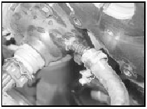
7.20a Disconnect the coolant hoses . . .
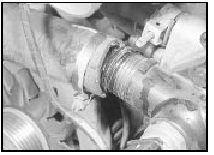
7.20b . . . from the thermostat housing
21 Disconnect the wiring plug from the cooling fan switch mounted in the thermostat housing (see illustration).
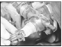
7.21 Disconnect the cooling fan switch wiring plug
22 Unscrew the three securing bolts, and withdraw the thermostat housing (see illustration).
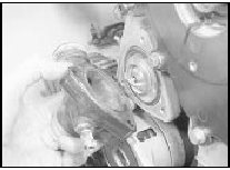
7.22 Withdrawing the thermostat housing
23 Manipulate the thermostat from the inlet manifold, and recover the O-ring. If it is necessary to prise the thermostat out, take care not to damage the surface of the housing in the inlet manifold.
24 Refitting is a reversal of removal, bearing in mind the following points.
25 Ensure that the O-ring seal is correctly fitted around the edge of the thermostat.
26 When fitting the thermostat to the inlet manifold, ensure that the relief valve is located in the 12 o’clock position (see illustration).
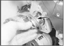
7.26 Thermostat relief valve (arrowed) should be in the 12 o’clock position
27 Tighten the thermostat housing securing bolts to the specified torque.
28 Refill the cooling system.
Thermostat - testing
1 To test the thermostat, suspend it by a piece of string in a container of water (see illustration).
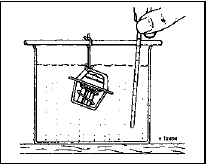
8.1 Testing the thermostat opening temperature
2 Gradually heat the water, and using a thermometer with a range of at least 100ºC, note the temperature at which the thermostat starts to open.
3 Remove the thermostat from the water and check that it is fully closed when cold.
4 Renew the thermostat if the opening temperature is not as given in the Specifications, or if the unit does not fully close when cold.
See also:
Turbocharger - general description
Escort RS Turbo models are equipped with
an exhaust driven turbocharger, which is a
device designed to increase the engine’s
power output without increasing exhaust
emissions or adversely affectin ...
Cargo area (P100 models) - removal and refitting
Note: A suitable lifting crane and tackle will be
required for this operation.
Removal
1 Disconnect the battery negative lead.
2 Remove the fuel filler cap, then drain the
fuel tank.
3 Remove th ...
