Exhaust system - inspection, removal and refitting
Inspection
1 The exhaust system should be examined for
leaks, damage, and security at regular
intervals. To do this, apply the handbrake, then
start the engine and allow it to idle. Lie down on
each side of the vehicle in turn and check the
full length of the exhaust system for leaks,
while an assistant temporarily places a wad of
cloth over the tailpipe. If a leak is evident, stop
the engine and use a proprietary repair kit to
seal it. If an excessive leak or damage is
evident, renew the relevant section of the
exhaust system. Check the rubber mountings
for deterioration and renew if necessary.
Removal
2 To remove the exhaust system, jack up the
front and rear of the vehicle and support on
axle stands (see “Jacking and Vehicle
Support”).
3 If desired, the exhaust downpipe can be removed independently of the remainder of the system, and similarly the main part of the system can be removed, leaving the downpipe in place.
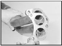
4 To remove the downpipe, unscrew the securing nuts and disconnect the downpipe from the manifold. Recover the gasket.
Unscrew the two nuts and bolts, and separate the downpipe flanged joint from the remainder of the system. Withdraw the downpipe (see illustrations).
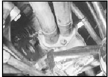
27.4a Exhaust downpipe-to-manifold flanged joint
viewed from underneath vehicle
27.4b Exhaust downpipe-to-main system flanged joint
5 To remove the main section of the exhaust system leaving the downpipe in place, unscrew the two securing nuts and bolts and separate the flanged joint from the downpipe.
Unhook the rubber mountings and withdraw the system from underneath the vehicle. The number and type of rubber mountings varies according to model (see illustrations).
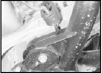
27.5a Rear exhaust section mounting - Hatchback model
27.5b Rear exhaust mounting - P100 model
If necessary to avoid confusion, note how the mountings are fitted to enable correct refitting. Note that on P100 models the system must be manipulated to pass over the rear axle.
Refitting
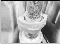
6 Refitting is a reversal of removal, but ensure
that all mating faces are clean, and fit a new
gasket between the downpipe and manifold
(see illustration).
27.6 Fit a new downpipe-to-manifold gasket
Do not fully tighten the joint fittings until the system is in position and correctly aligned in its mountings under the vehicle. Ensure that no part of the exhaust system is closer than 25.0 mm (1.0 in) to the underbody.
7 Service replacement exhaust systems are available in three sections; downpipe, centre section and rear section. The service replacement sections fit together using socket joints, therefore the centre section of a production exhaust system cannot be renewed without also renewing the rear section.
8 To renew the centre and/or rear section(s) of the exhaust system, first remove the main system as described in paragraph 5.
9 To fit a service replacement rear section to a production system, use a hacksaw to cut through the pipe at the applicable point shown (see illustrations).
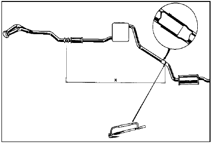
27.9a Cutting point when fitting a service replacement exhaust system section
- Saloon, Hatchback and Estate models
X = 1639 mm for all models up to 1987 except 1.3 and 1.6 litre Hatchback X = 1681 mm for 1.3 and 1.6 litre Hatchback models up to 1987 X = 2063 mm for all models from 1987
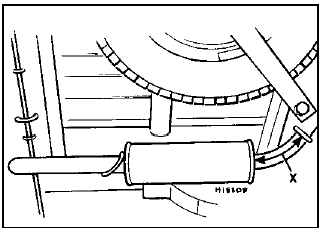
27.9b Cutting point when fitting a service replacement exhaust system section
- P100 models
X = 226 mm
Apply exhaust
sealant to the mating surfaces of the two
sections, then push the two sections together
and fit a U-bolt clamp to the centre of the
joint. Do not fully tighten the U-bolt clamp
nuts until the system is in position and
correctly aligned in its mountings under the
vehicle.
10 To renew a service replacement section, unscrew the nuts and remove the U-bolt clamp from the joint. Tap around the joint to break the seal, and separate the centre and rear sections. Ensure that the joint mating surfaces are clean, then apply exhaust sealant, push the new section onto the remaining section, and fit the U-bolt clamp to the centre of the joint. Do not fully tighten the U-bolt clamp nuts until the system is in position and correctly aligned in its mountings under the vehicle.
Vacuum valves, ported vacuum switches and fuel traps - removal and refitting
Refer to Chapter 5, Section 22 (see illustration).
28.1 Low vacuum enrichment ported vacuum switch location in inlet manifold -
model with Weber 2V carburettor
See also:
Crankshaft and bearings - examination and renovation
1.8 litre (R2A type)
1 Examine the bearing surfaces of the
crankshaft for scratches or scoring and, using
a micrometer, check each journal and
crankpin for ovality. Where this is found to be
in e ...
Door lock - removal and refitting
Models up to 1990
1 Remove the door inner trim panel.
2 Where necessary for improved access, peel
back the waterproof plastic sheet from the
door.
3 Withdraw the window channel extension
through ...
Cold start valve - removal and refitting
Note: Refer to the precautions at the end of
Section 1 before proceeding.
K-Jetronic system
Removal
1 Disconnect the battery earth lead.
2 Detach the electrical wiring multi-plug from
the valve ...
