Front hub carrier - removal and refitting
Note: A balljoint separator tool will be required for this operation.
Removal
1 Loosen the relevant front roadwheel nuts,
apply the handbrake, jack up the front of the
vehicle and support on axle stands (see
“Jacking and Vehicle Support”).
2 Remove the roadwheel. On P100 models mark the position of the roadwheel in relation to one of the wheel studs before removal.
3 Remove the front brake caliper but do not disconnect the hydraulic hose. Support the caliper on an axle stand, or suspend it with wire from the coil spring to avoid straining the hose.
4 Mark the position of the brake disc in relation to the drive flange, and on Saloon, Hatchback and Estate models, remove the retaining screw or spire washer(s), as applicable, and remove the disc. On P100 models, unscrew the five retaining nuts and remove the wheel adapter plate and disc.
5 Where applicable, unbolt the ABS wheel sensor from the hub carrier and unplug the wiring connector. Place the sensor to one side.
6 Remove the split pin and unscrew the castellated nut securing the tie-rod end to the hub carrier. Using a balljoint separator tool, disconnect the tie-rod end from the hub carrier.
7 Repeat the procedure given in the previous paragraph for the lower arm-to-hub carrier balljoint.
8 Unscrew and remove the pinch-bolt which secures the hub carrier to the strut (see illustration). Using a suitable lever, such as a cold chisel, lever the hub carrier clamp legs and wedge them apart. Withdraw the hub carrier from the strut.
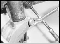
5.8 Unscrewing the hub carrier-to-strut pinch-bolt
Refitting
9 Refitting is a reversal of removal, but use
new split pins on the castellated nuts, and
align the previously made marks on the brake
disc and hub. Tighten all fixings to the
specified torque.
10 On P100 models align the previously made marks on the roadwheel and wheel stud.
See also:
Engine/transmission mountings - removal and refitting
Pre-1986 models
1 The engine mountings can be removed if
the weight of the engine/transmission is first
taken by one of the three following methods.
2 Either support the engine under the sump
usi ...
Wiring diagrams
Notes, tables, wire colours and key to wiring diagrams. Models up to 1987
Notes, tables, wire colours and key to wiring diagrams. Models up to 1987
Key to wiring diagrams (continued). Models up to ...
Safety restraints for children
See the following sections for directions on how to properly use safety
restraints for children. Also see Air bag supplemental restraint system
(SRS) in this chapter for special instructions about u ...
