Wheel sensor (ABS) - removal and refitting
Note: A new O-ring must be used when refitting a sensor.
Front wheel sensor
1 Apply the handbrake, loosen the relevant
front roadwheel nuts, then jack up the front of
the vehicle and support on axle stands (see
“Jacking and Vehicle Support”). Remove the
roadwheel.
2 Working under the bonnet, unclip the ABS wiring loom from the chassis side member, and disconnect the wheel sensor wiring plug.
3 Unscrew the mounting bolt and withdraw the sensor (see illustration).
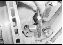
22.3 Unscrew the mounting bolt and withdraw the front wheel sensor - ABS
4 Refitting is a reversal of removal, bearing in mind the following points.
5 Clean the bore in the hub carrier, and smear the bore and the sensor with lithium based grease.
6 Use a new O-ring seal when refitting the sensor.
Rear wheel sensor
7 Chock the front wheels, loosen the relevant
rear roadwheel nuts, then jack up the rear of
the vehicle and support on axle stands.
Release the handbrake and remove the roadwheel.
8 Working inside the vehicle, lift up the rear seat cushion, then remove the side kick panel and fold the carpet forwards to gain access to the wheel sensor wiring plug (see illustrations).
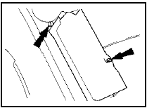
22.8a Remove the side kick panel (securing screws arrowed) for access to the
rear wheel sensor wiring plug - ABS
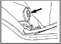
22.8b Rear wheel sensor wiring plug (arrowed) - ABS
9 Remove the wiring plug from its clip, and disconnect it.
10 Prise out the floor panel grommet, then feed the sensor wiring through the floor panel.
11 Free the handbrake cable from its clip on the suspension lower arm.
12 Where applicable, disconnect the wiring to the disc pad wear sensor.
13 Unscrew and remove the bolt from the forward caliper guide pin, while holding the pin stationary with a spanner.
14 Swing the caliper rearwards to gain access to the wheel sensor.
15 Unscrew the bolt securing the sensor to its mounting bracket.
16 Refitting is a reversal of removal, bearing in mind the following points.
17 Clean the bore in the sensor mounting bracket, and smear the bore and the sensor with lithium based grease.
18 Use a new O-ring seal when refitting the sensor.
See also:
Radiator grille panel - removal and refitting
Models up to 1987
1 With the bonnet raised, remove the four
grille panel securing screws from the top of
the front panel.
2 Lift the grille panel from its lower mounting
bushes, and withdraw it f ...
Front suspension lower arm (pressed steel type) - removal,
overhaul and refitting
1 The pressed steel type suspension is only
fitted to pre-May 1983 1.1 litre models (see
illustration).
4.1 Pressed steel type lower arm components
A Lower arm
B Tie-bar
C Retaining bolt
D Ba ...
Brake hydraulic system (conventional braking system) - bleeding
Caution: Refer to the
precautions in Section 1.
General
1 If any of the hydraulic components in the
braking system have been removed or
disconnected, or if the fluid level in the
reservoir has b ...
