Fuses and relays - location and renewal
Location
1 The main fuses and relays are located in a
box in the engine compartment on the righthand
side of the bulkhead. The circuits
protected are identified by symbols on the
underside of the fusebox cover. On certain
models, additional relays and fuses are located
in various positions beneath the facia panels. If
uncertain of the location of an auxiliary relay or
fuse, it is suggested that a Ford dealer is
consulted, as the relay and fuse locations vary
substantially depending on model.
Renewal
2 Always renew a fuse with one of identical
rating and never renew it more than once
without finding the source of the trouble
(usually a short circuit). Always switch off the
ignition before renewing a fuse or relay, and
when renewing the wiper motor fuse keep the
hands clear of the wiper linkage as it may
return to the parked position. Note that the
fuses are colour-coded as follows:
10A Red
15A Blue
20A Yellow
25A Natural
10A Green
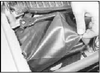
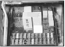
3 Access to the fuses and relays in the
fusebox is gained by removing the loose
cover and spring clip (if fitted), pulling the
plastic clip and removing the cover. All fuses
and relays are a push fit (see illustrations).

3.3a Remove the loose cover for access to the fusebox cover

3.3b Fusebox cover removed to expose fuses and relays (1.8 CVH model shown)
The fuse/relay plate can be released from the fusebox for access to the wiring by carefully levering the plastic lugs around the perimeter of the plate.
4 For details of direction indicator/hazard warning flasher relay removal and refitting, refer to the relevant Section of this Chapter.
See also:
Exterior lamps - removal and refitting
Headlamp
Removal
1 On pre-1986 models, remove the radiator
grille as described in Chapter 11.
2 Working in the engine compartment,
disconnect the headlamp wiring multi-plug
and remove the sidela ...
Engine mountings - renewal
1 The engine mountings incorporate
hydraulic dampers and must be renewed if
excessive engine movement is evident.
2 Working in the engine compartment,
unscrew the central nuts securing the engine
...
Front suspension strut - removal, overhaul and refitting
Note: A spring compressor tool will be
required if the strut is to be dismantled.
Removal
1 Loosen the relevant front roadwheel nuts,
apply the handbrake, jack up the front of the
vehicle and sup ...
