Trip computer components - removal and refitting
1 Disconnect the battery negative lead
Computer module
2 Remove the single screw from the top edge
of the facia panel in which the module is
housed, then withdraw the facia panel.
3 Remove the four now exposed securing screws, disconnect the wiring plug, and carefully withdraw the module. On later models a retaining lug must be depressed before the wiring plug can be disconnected.
4 Where applicable, the mounting brackets can be removed from the module by unscrewing the securing nuts.
5 If necessary, the illumination bulb can be removed from the module by twisting the bulbholder anti-clockwise using a pair of longnosed pliers. The bulb is a push-fit in the holder.
6 Refitting is a reversal of removal.
Speed sender unit
Models up to 1987
7 The speed sender unit is located in the
engine compartment on the right-hand side of
the bulkhead.
8 Disconnect the plug from the sender unit.
9 Unscrew the two knurled nuts from the sender unit and disconnect the two speedometer cables.
10 Remove the three securing screws and remove the bracket and sender unit.
11 Unscrew and remove the securing nut and washer, and separate the sender unit from the bracket.
12 Refitting is a reversal of removal.
Models from 1987
13 Detach the wiring, hose retainers and
cover panel from the bulkhead to gain access
to the sender unit.
14 Proceed as shown in paragraphs 7 to 9.
15 Remove the retaining nut and washer and withdraw the sender unit.
16 Refitting is a reversal of removal.
Fuel flow sensor unit
Carburettor models
17 The fuel flow sensor is located on the lefthand
side of the engine compartment (see
illustration).
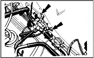
22.17 Trip computer fuel flow sensor unit location - carburettor models
up to 1987. Bracket retaining screws arrowed
18 Disconnect the wiring plug from the sensor unit.
19 Refer to the “Safety first!” Section at the front of the manual, and the precautions in Chapter 4, then disconnect the fuel pipes from the sensor unit. Note that on models up to 1987 there are three fuel pipe connections, and on models from 1987 there are two fuel pipe connections. Be prepared for fuel spillage.
20 Remove the three securing screws and withdraw the bracket and sender unit.
21 Unscrew the four nuts and separate the sender unit from the bracket.
22 Refitting is a reversal of removal, but ensure that the flow direction arrows on the fuel inlet and outlet ports are correctly orientated, and that the arrow on the rear of the unit points to the top.
Fuel injection models
23 The sensor is located on the left-hand
side of the engine compartment.
24 Disconnect the wiring plug from the sensor unit.
25 Refer to the “Safety first!” Section at the front of the manual, and the precautions in Chapter 4, then unscrew the two union nuts and disconnect the fuel pipes from the sensor unit. Be prepared for fuel spillage.
26 Remove the two securing screws and withdraw the sensor unit.
27 Refitting is a reversal of removal, but ensure that the No 2 injector fuel pipe is fitted to the sensor unit outlet port marked with an arrow, and ensure that the union washers are in place (see illustration). Tighten the fuel pipe unions to the specified torque.
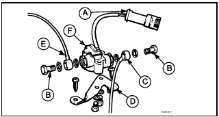
22.27 Trip computer fuel flow sensor unit - fuel injection models
A Wiring plug
B Hollow bolts
C Inlet port banjo connector
D Bracket
E Outlet port banjo connector
F Sensor unit
See also:
Interior mirror - removal and refitting
Removal
1 The interior mirror is bonded to the
windscreen glass. If it must be removed, grip
the mirror firmly and push it forward to break
the adhesive bond.
2 When refitting the mirror, the fol ...
Handbrake cable - adjustment
Note: Where fitted, the adjuster locking pin
must be renewed on completion of
adjustment.
Conventional braking system
(except P100 models)
1 The handbrake cable is normally
self-adjusting in use ...
Manual gearbox oil level check (Every 12 000 miles (20 000 km) or 12 months)
1 Place the vehicle over a pit, or raise and
support it at front and rear. The vehicle must
be level for an accurate check.
2 If the gearbox is hot after a run, allow it to
cool for a few minutes. ...
