Wiring diagrams
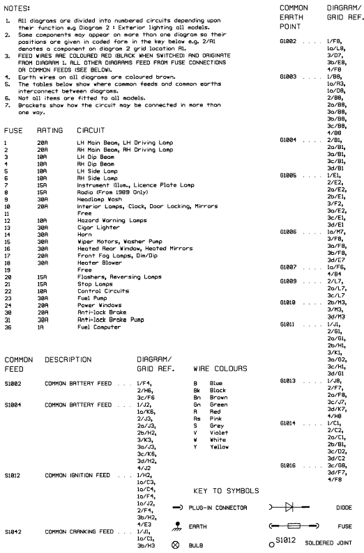
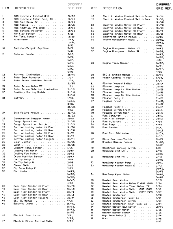
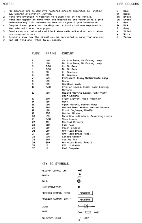
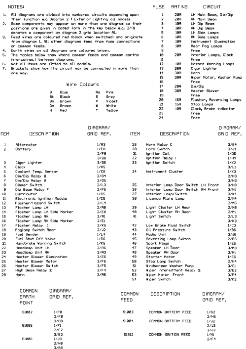
Notes, tables, wire colours and key to wiring diagrams. Models up to 1987
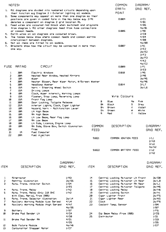
Notes, tables, wire colours and key to wiring diagrams. Models up to 1987
Key to wiring diagrams (continued). Models up to 1987
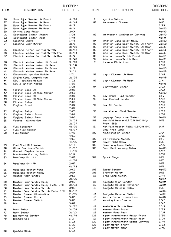
Key to wiring diagrams (continued). Models up to 1987
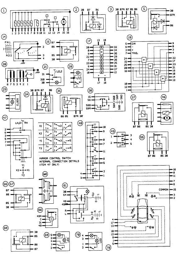
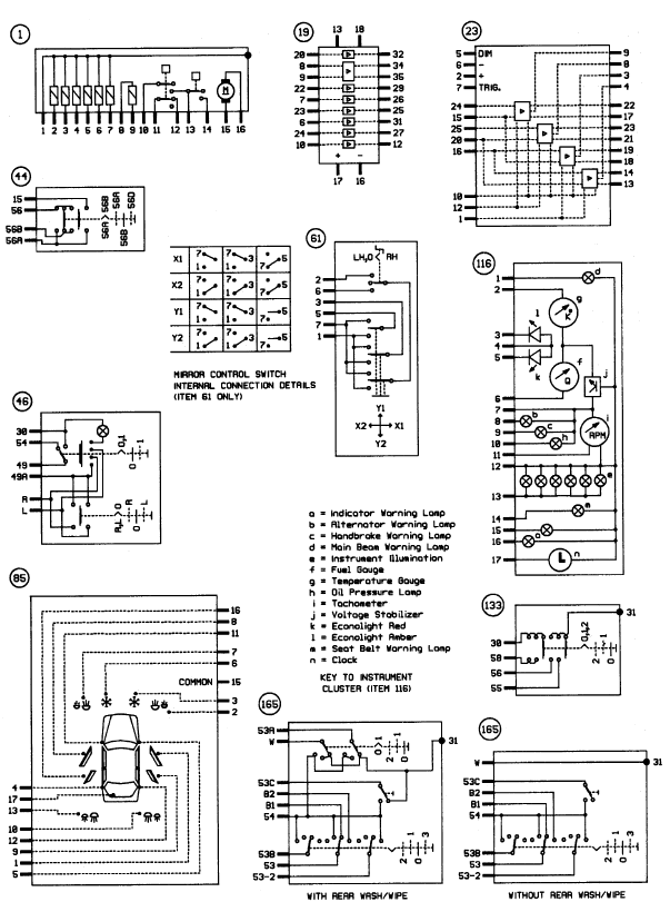
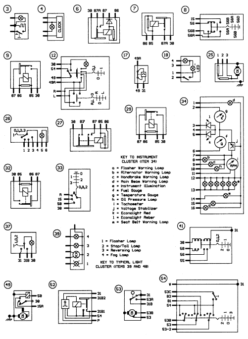
Internal connection details. Models up to 1987
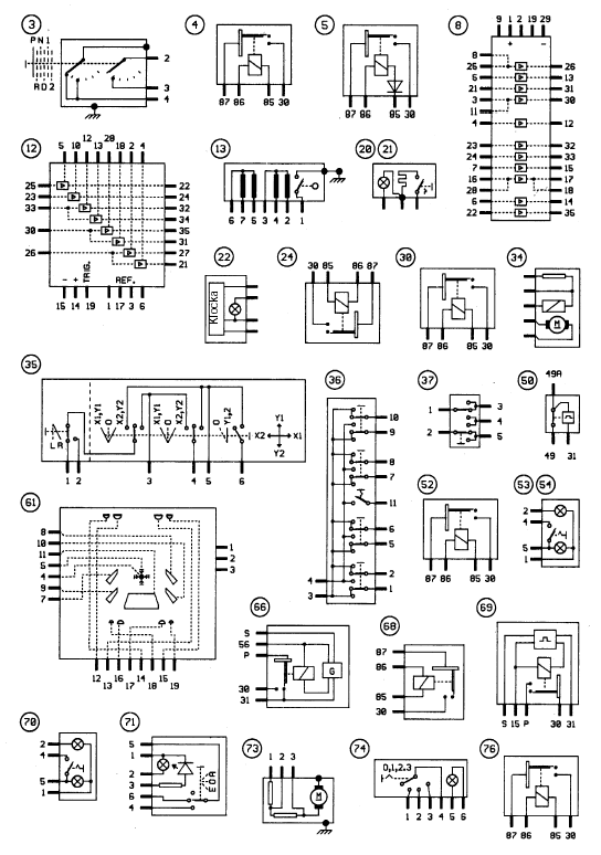
Internal connection details. Models up to 1987
Internal connection details (continued). Models up to 1987
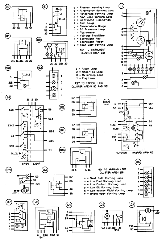
Internal connection details (continued). Models up to 1987
Diagram 1. Starting, charging and ignition (except fuel injection). Models up to 1987
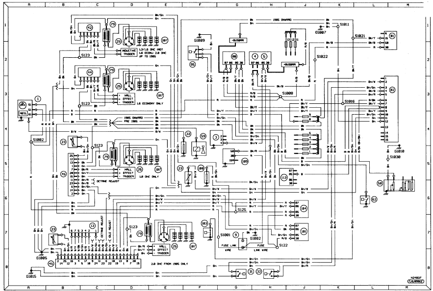
Diagram 1. Starting, charging and ignition (except fuel injection). Models up to
1987
Diagram 2. Exterior lighting. Models up to 1987
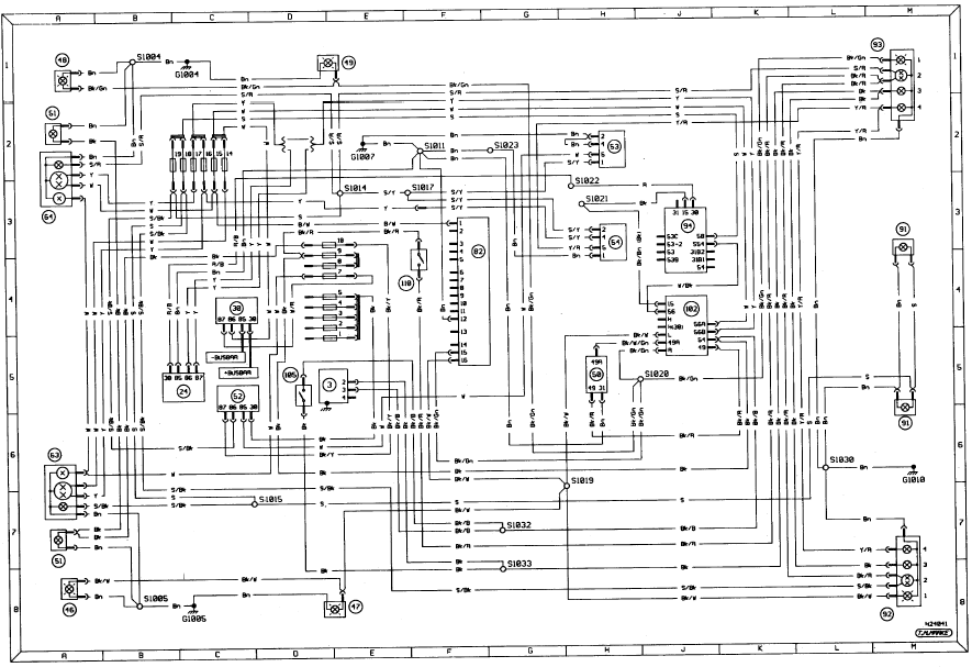
Diagram 2. Exterior lighting. Models up to 1987
Diagram 2a. Interior lighting. Models up to 1987
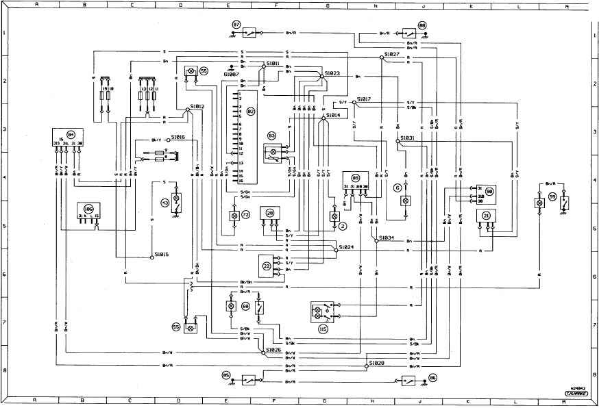
Diagram 2a. Interior lighting. Models up to 1987
Diagram 3. Ancillary circuits (low series). Models up to 1987
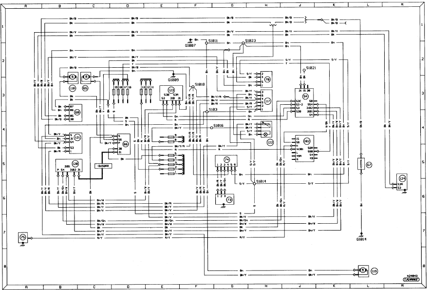
Diagram 3. Ancillary circuits (low series). Models up to 1987
Diagram 3a. Additional ancillary circuits (high series only). Models up to 1987
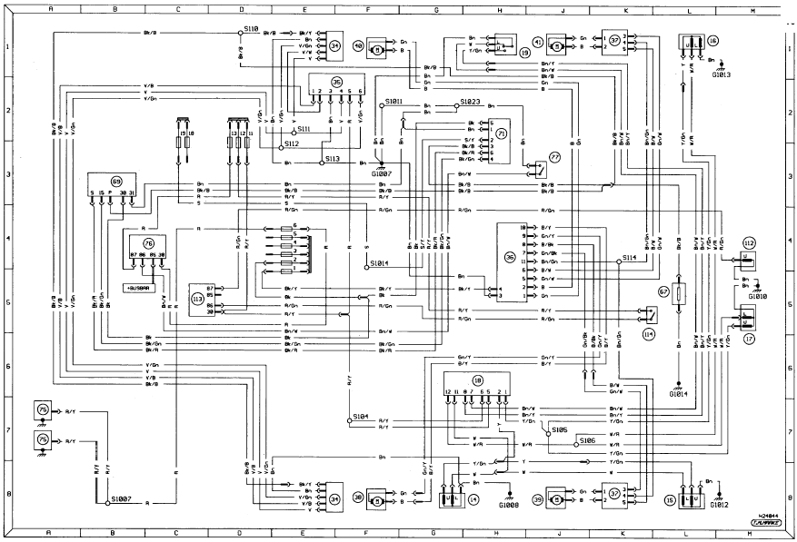
Diagram 3a. Additional ancillary circuits (high series only). Models up to 1987
Diagram 4. Auxiliary warning system. Models up to 1987
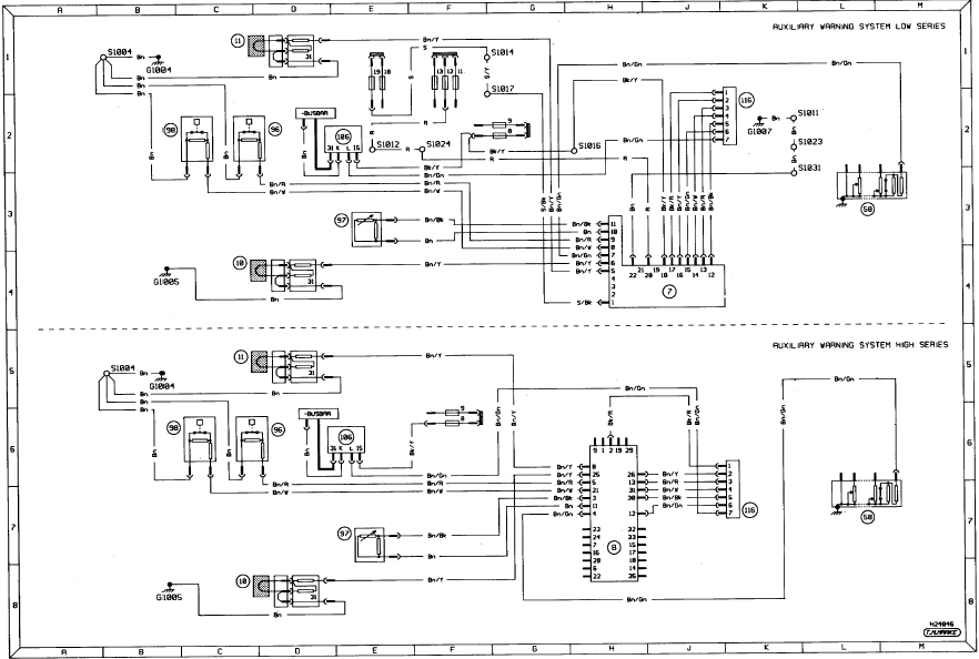
Diagram 4. Auxiliary warning system. Models up to 1987
Diagram 4a. Graphic display system and fuel computer. Models up to 1987
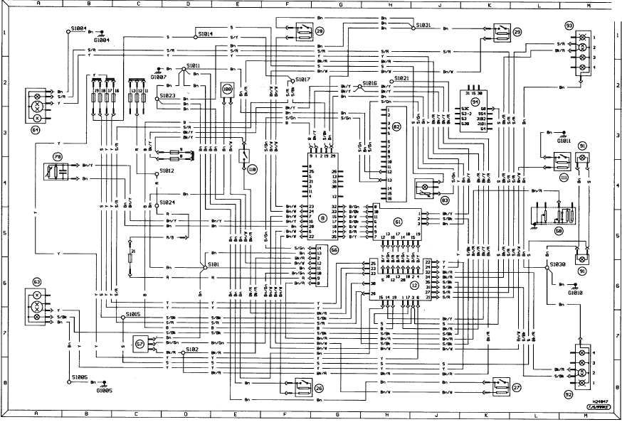
Diagram 4a. Graphic display system and fuel computer. Models up to 1987
Notes, tables, wire colours and key to symbols on wiring diagrams. Models from 1987 to May 1989
Notes, tables, wire colours and key to symbols on wiring diagrams. Models from
1987 to May 1989
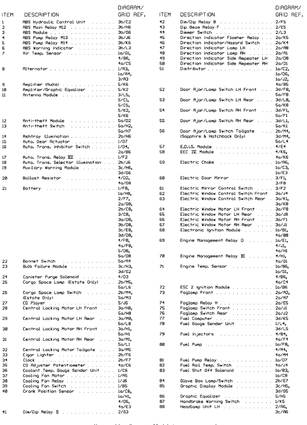
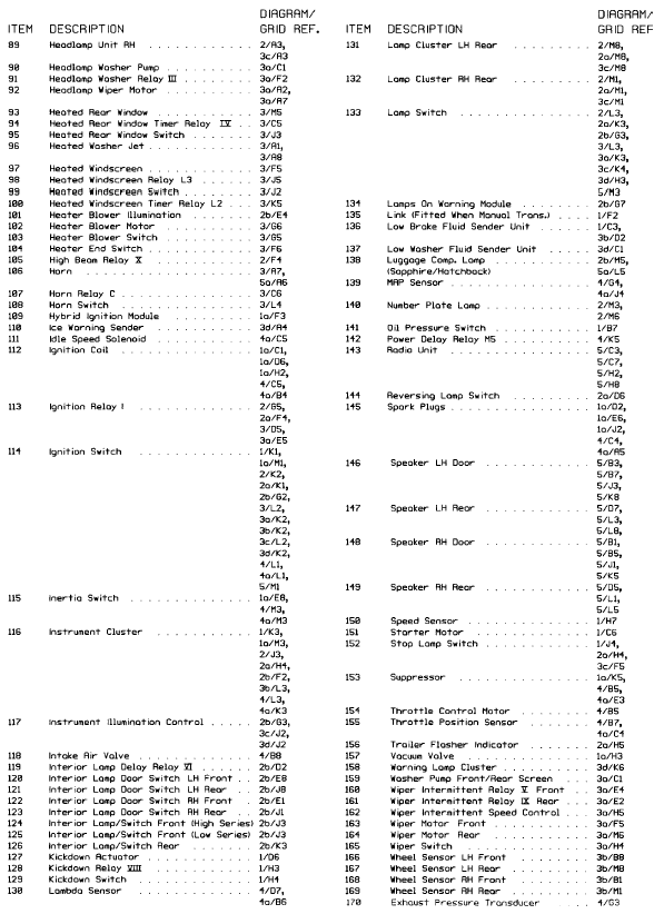
Key to wiring diagrams. Models from 1987 to May 1989
Key to wiring diagrams. Models from 1987 to May 1989
Key to wiring diagrams (continued). Models from 1987 to May 1989
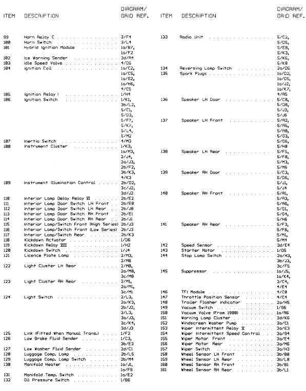
Key to wiring diagrams (continued). Models from 1987 to May 1989
Internal connection details. Models from 1987 to May 1989
Internal connection details. Models from 1987 to May 1989
Internal connection details (continued). Models from 1987 to May 1989
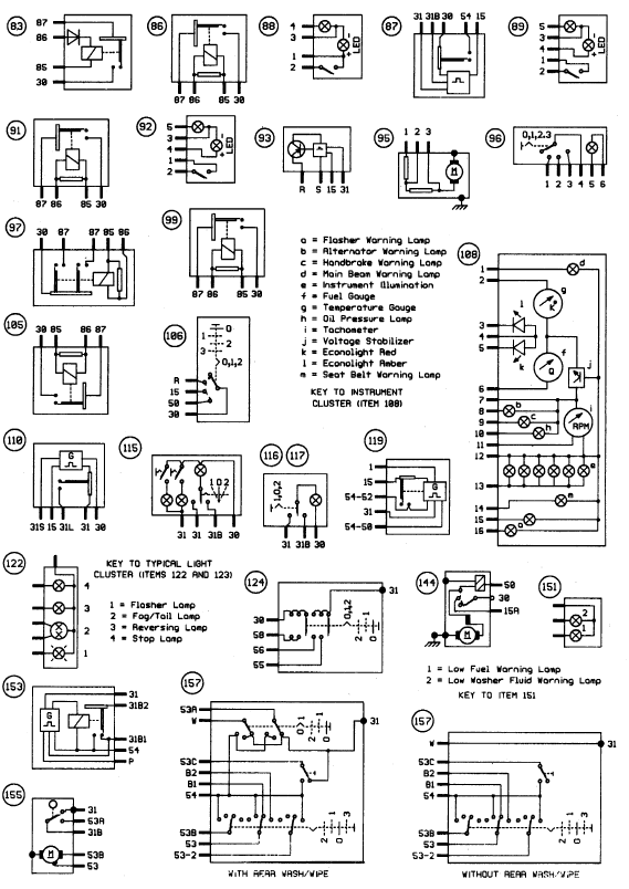
Internal connection details (continued). Models from 1987 to May 1989
Diagram 1. Starting, charging and warning lamps. Models from May 1987 to May 1989
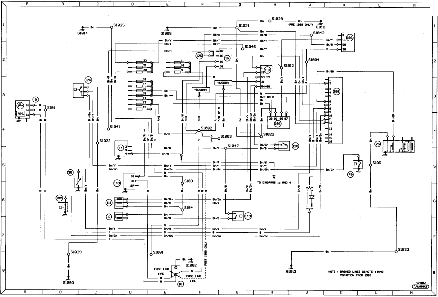
Diagram 1. Starting, charging and warning lamps. Models from May 1987 to May
1989
Diagram 1a. Ignition variations. Carburettor models from 1987 to May 1989
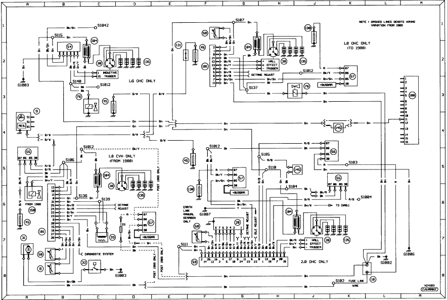
Diagram 1a. Ignition variations. Carburettor models from 1987 to May 1989
Diagram 2. Exterior lighting - head/sidelamps. Models from 1987 to May 1989
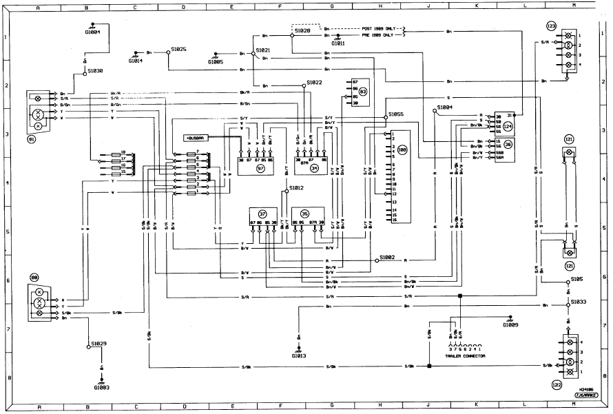
Diagram 2. Exterior lighting - head/sidelamps. Models from 1987 to May 1989
Diagram 2a. Exterior lighting - signal warning lamps. Models from 1987 to May 1989
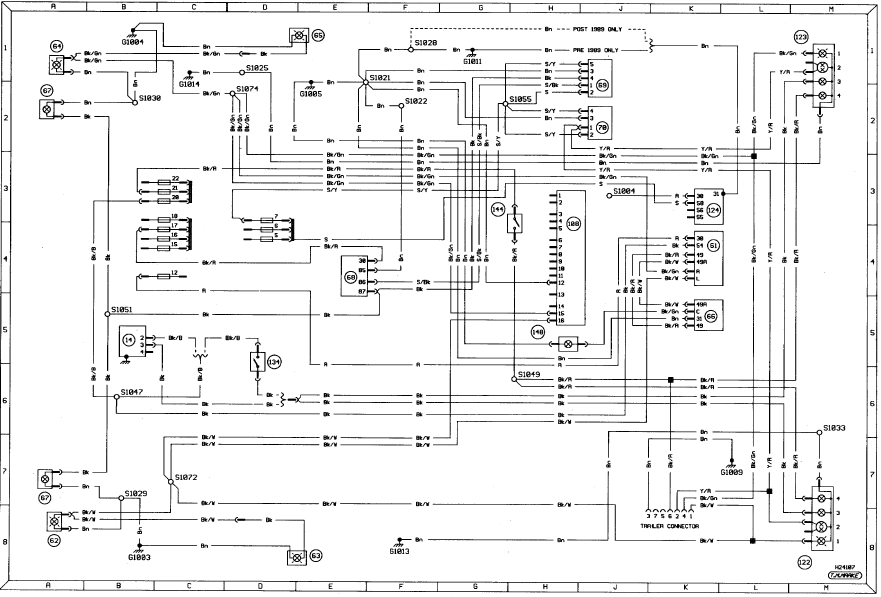
Diagram 2a. Exterior lighting - signal warning lamps. Models from 1987 to May
1989
Diagram 2b. Interior lighting. Models from 1987 to May 1989
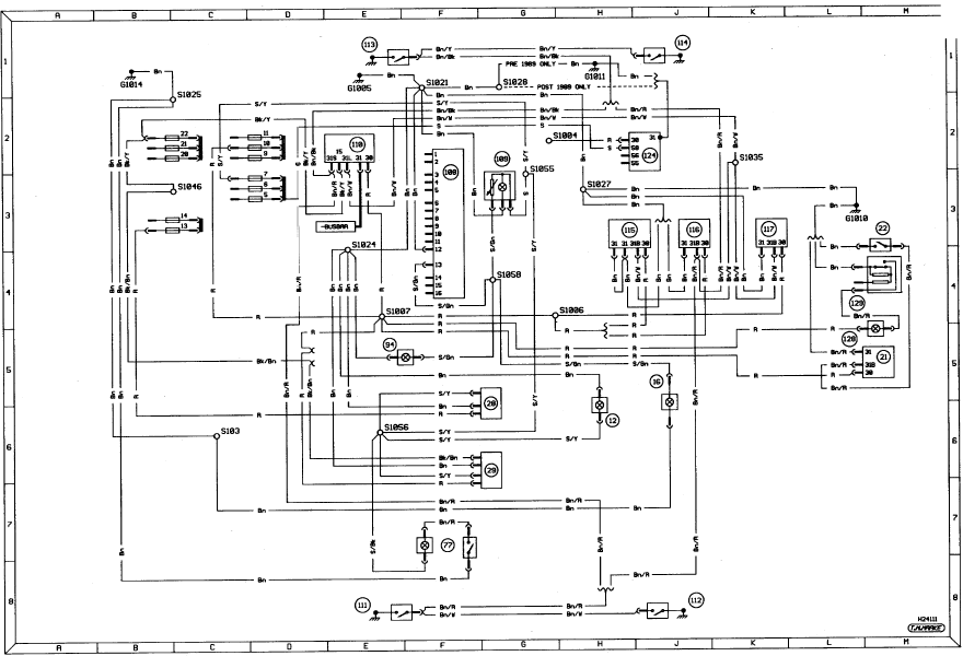
Diagram 2b. Interior lighting. Models from 1987 to May 1989
Diagram 3. Ancillary circuits - horn, heater blower, heated mirrors and screens. Models from 1987 to May 1989
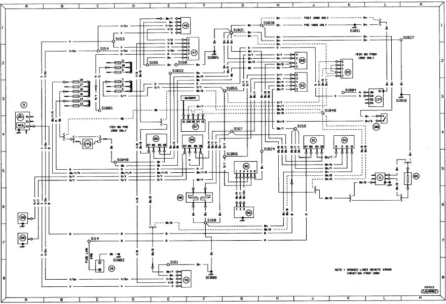
Diagram 3. Ancillary circuits - horn, heater blower, heated mirrors and screens.
Models from 1987 to May 1989
Diagram 3a. Ancillary circuits - wash/wipe, central locking and electric windows. Models from 1987 to May 1989
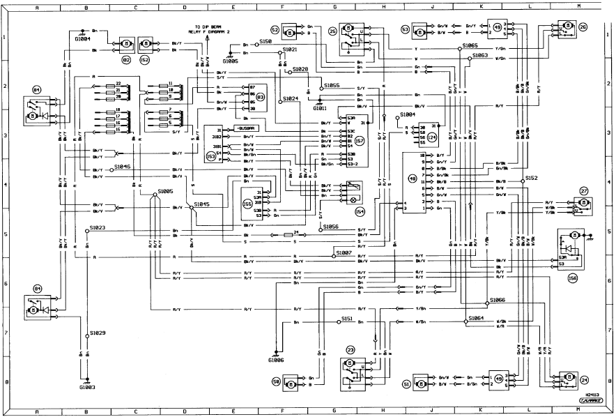
Diagram 3a. Ancillary circuits - wash/wipe, central locking and electric
windows. Models from 1987 to May 1989
Diagram 3b. Anti-lock braking system. Models from 1987 to May 1989
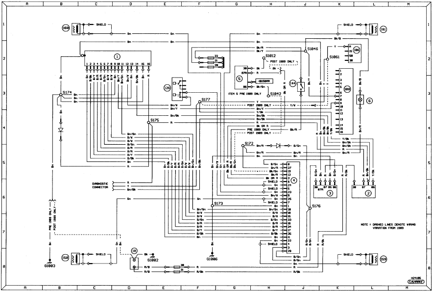
Diagram 3b. Anti-lock braking system. Models from 1987 to May 1989
Diagram 3c. Graphic display system - bulb failure. Models from 1987 to May 1989
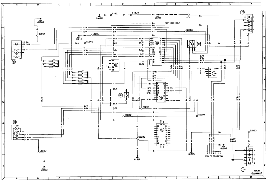
Diagram 3c. Graphic display system - bulb failure. Models from 1987 to May 1989
Diagram 3d. Graphic display system - auxiliary warning, door ajar and fuel computer. Models from 1987 to May 1989
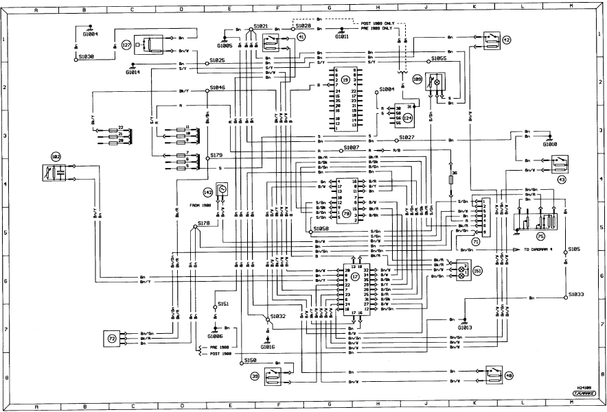
Diagram 3d. Graphic display system - auxiliary warning, door ajar and fuel
computer. Models from 1987 to May 1989
Diagram 4. 2.0 Efi fuel injection and ignition. Models from 1987 to May 1989
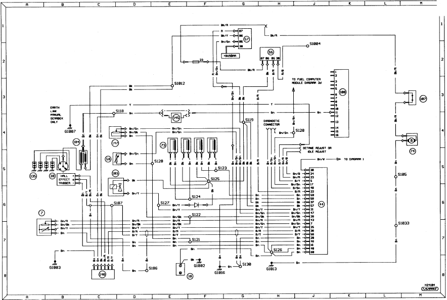
Diagram 4. 2.0 Efi fuel injection and ignition. Models from 1987 to May 1989
Diagram 5. In-car entertainment. Models from 1987 to May 1989
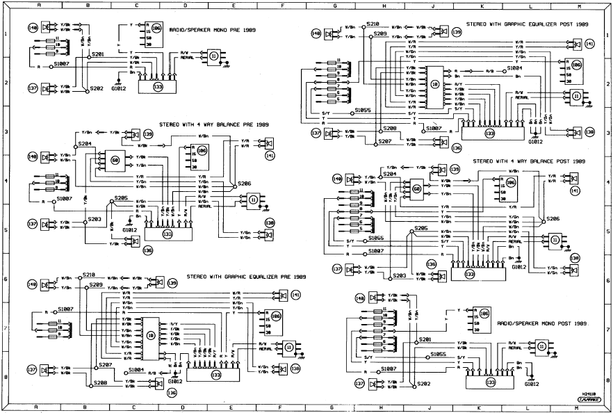
Diagram 5. In-car entertainment. Models from 1987 to May 1989
Notes, tables, wire colours and key to symbols on wiring diagrams. Models from 1990 onwards
Notes, tables, wire colours and key to symbols on wiring diagrams. Models from
1990 onwards
Key to wiring diagrams. Models from 1990 onwards
Key to wiring diagrams. Models from 1990 onwards
Key to wiring diagrams (continued). Models from 1990 onwards
Key to wiring diagrams (continued). Models from 1990 onwards
Internal connection details. Models from 1990 onwards
Internal connection details. Models from 1990 onwards
Diagram 1. Starting, charging automatic transmission and warning lamps. Models from 1990 onwards
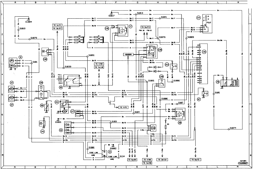
Diagram 1. Starting, charging automatic transmission and warning lamps. Models
from 1990 onwards
Diagram 1a. Ignition system for all carburettor models. Models from 1990 onwards
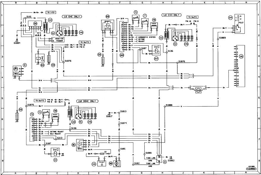
Diagram 1a. Ignition system for all carburettor models. Models from 1990 onwards
Diagram 2. Exterior lighting - head/sidelamps. Models from 1990 onwards
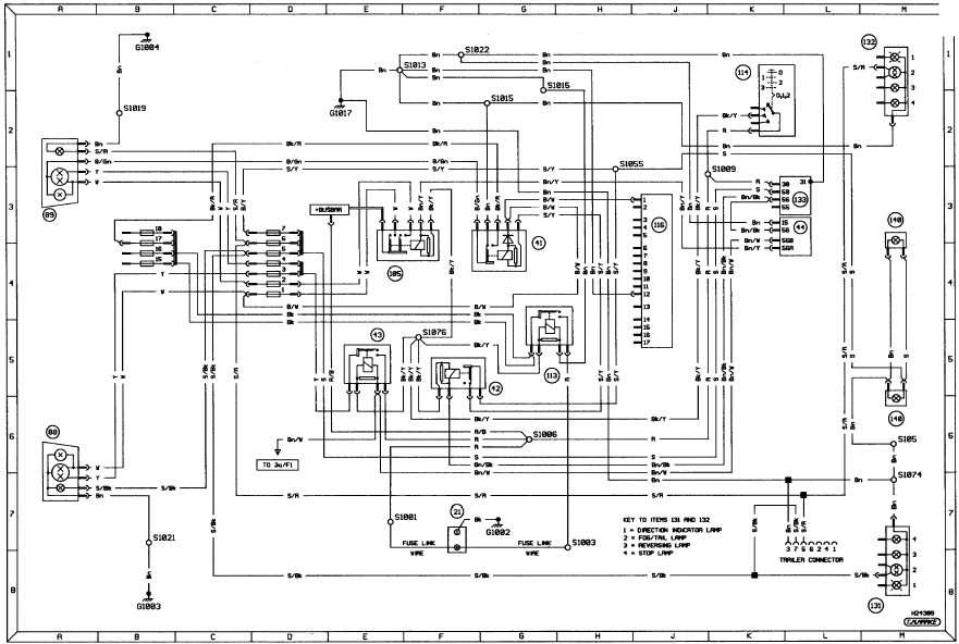
Diagram 2. Exterior lighting - head/sidelamps. Models from 1990 onwards
Diagram 2a. Exterior lighting - signal warning lamps. Models from 1990 onwards
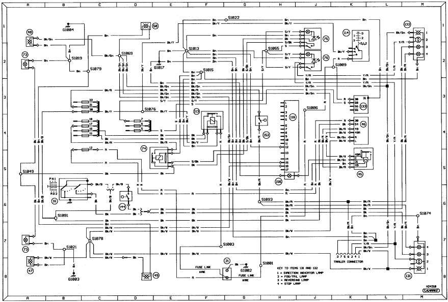
Diagram 2a. Exterior lighting - signal warning lamps. Models from 1990 onwards
Diagram 2b. Interior lighting. Models from 1990 onwards
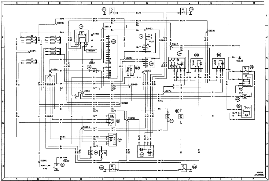
Diagram 2b. Interior lighting. Models from 1990 onwards
Diagram 3. Ancillary circuits - horn, heater blower, heated mirrors and screens. Models from 1990 onwards
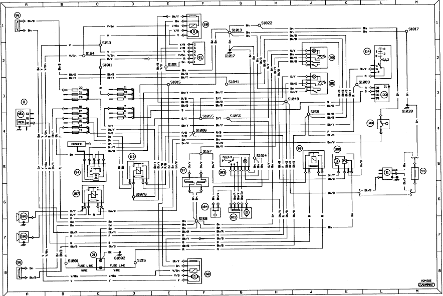
Diagram 3. Ancillary circuits - horn, heater blower, heated mirrors and screens.
Models from 1990 onwards
Diagram 3a. Ancillary circuits - wash/wipe, central locking and electric windows. Models from 1990 onwards
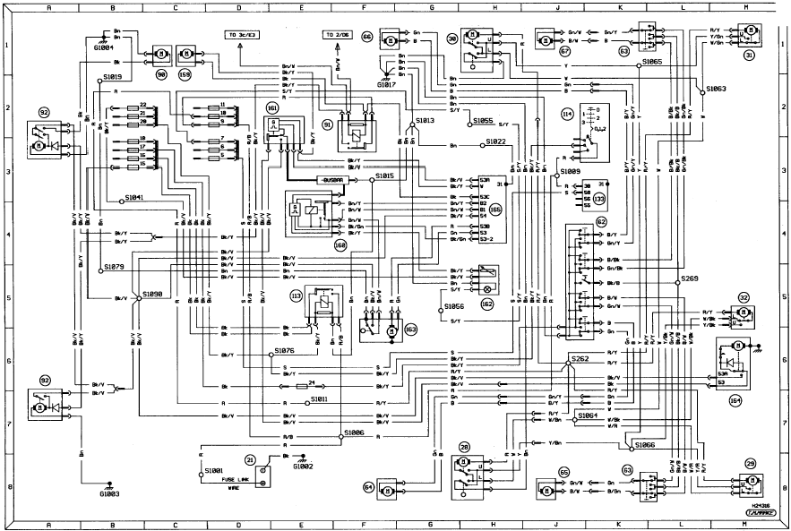
Diagram 3a. Ancillary circuits - wash/wipe, central locking and electric
windows. Models from 1990 onwards
Diagram 3b. Anti-lock braking system. Models from 1990 onwards
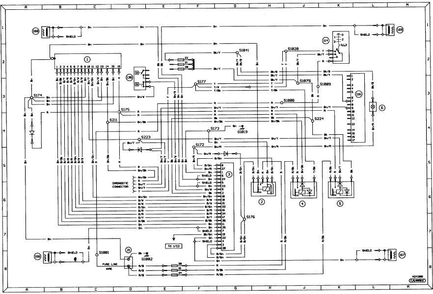
Diagram 3b. Anti-lock braking system. Models from 1990 onwards
Diagram 3c. Graphic display system - bulb failure. Models from 1990 onwards
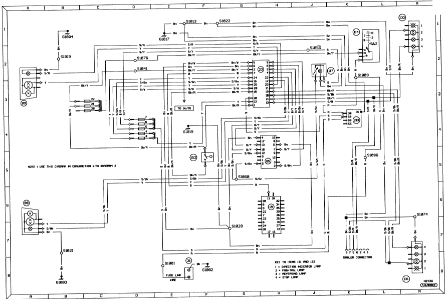
Diagram 3c. Graphic display system - bulb failure. Models from 1990 onwards
Diagram 3d. Graphic display system - auxiliary warning, door ajar and fuel computer. Models from 1990 onwards
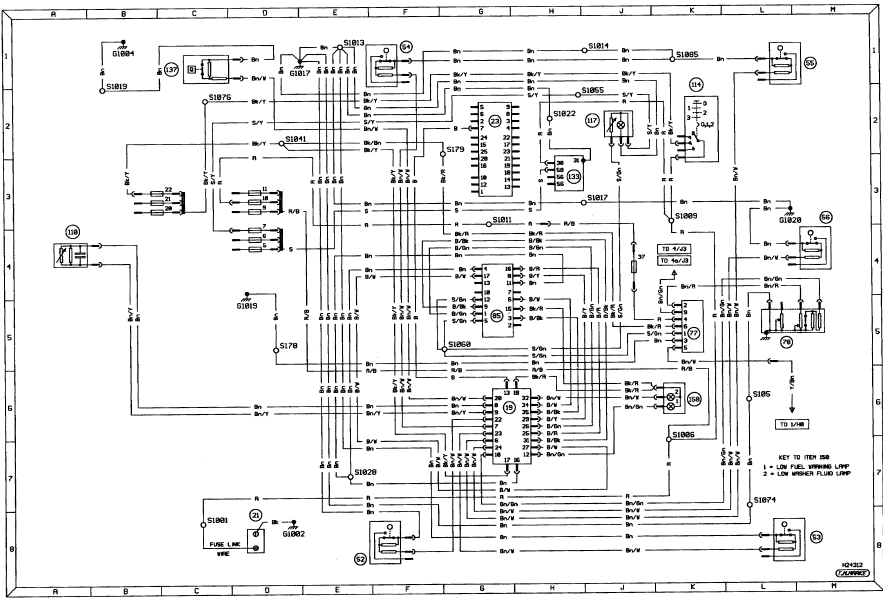
Diagram 3d. Graphic display system - auxiliary warning, door ajar and fuel
computer. Models from 1990 onwards
Diagram 4. 1.6 and 1.8 CVH engine CfI fuel injection and ignition systems. Models from 1990 onwards
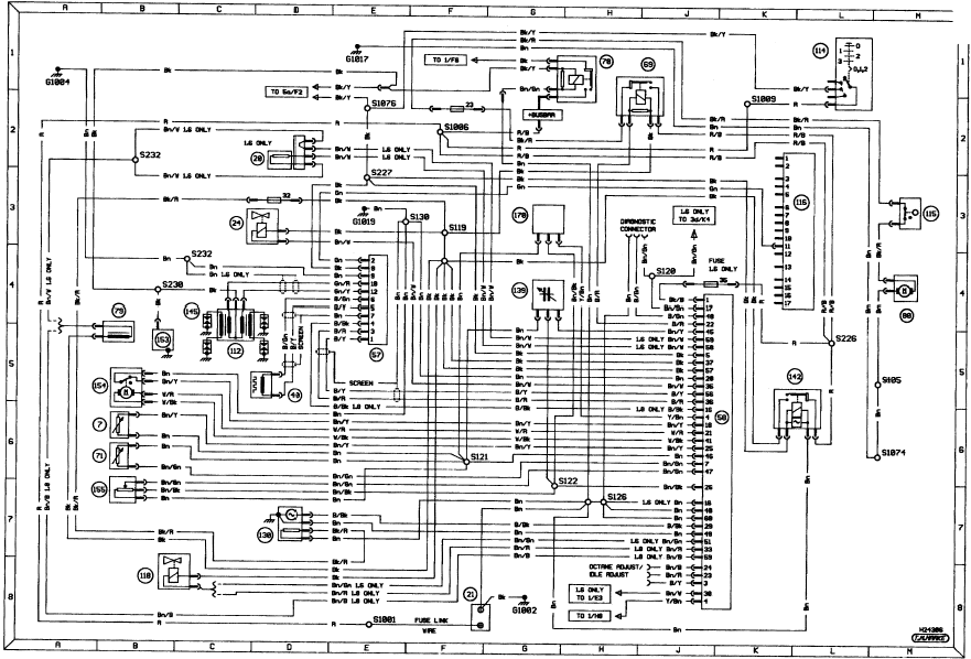
Diagram 4. 1.6 and 1.8 CVH engine CfI fuel injection and ignition systems.
Models from 1990 onwards
Diagram 4a. 2.0 litre DOHC engine EFI fuel injection and ignition systems. Models from 1990 onwards
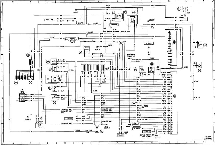
Diagram 4a. 2.0 litre DOHC engine EFI fuel injection and ignition systems.
Models from 1990 onwards
Diagram 5. In-car entertainment. Models from 1990 onwards
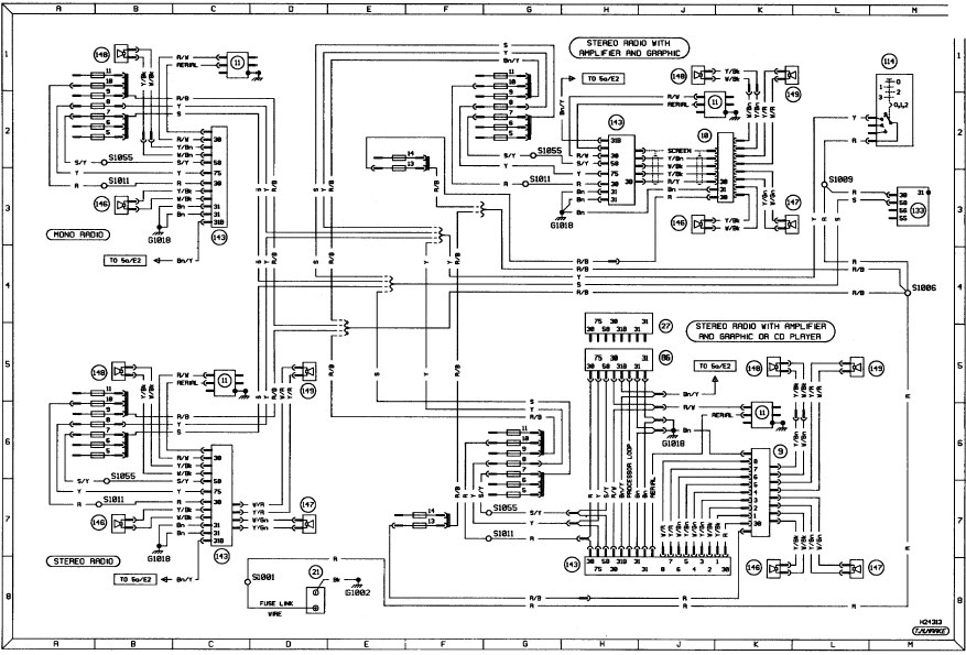
Diagram 5. In-car entertainment. Models from 1990 onwards
Diagram 5a. Anti-theft alarm. Models from 1990 onwards
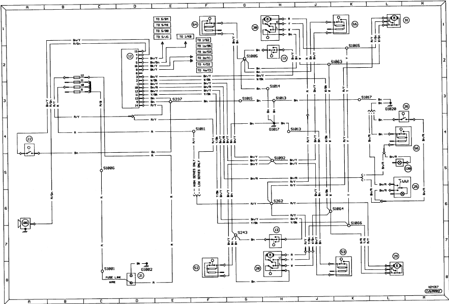
Diagram 5a. Anti-theft alarm. Models from 1990 onwards
Notes, tables, wire colours and key to wiring diagrams. P100 models from 1988 onwards
Notes, tables, wire colours and key to wiring diagrams. P100 models from 1988
onwards
Internal connection details. P100 models from 1988 onwards
Internal connection details. P100 models from 1988 onwards
Diagram 1. Starting, charging and ignition. P100 models from 1988 onwards
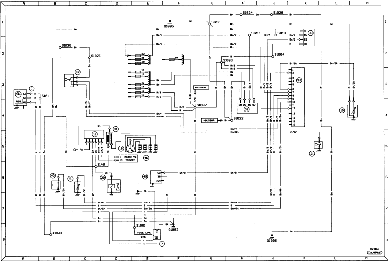
Diagram 1. Starting, charging and ignition. P100 models from 1988 onwards
Diagram 2. Exterior lighting. P100 models from 1988 onwards
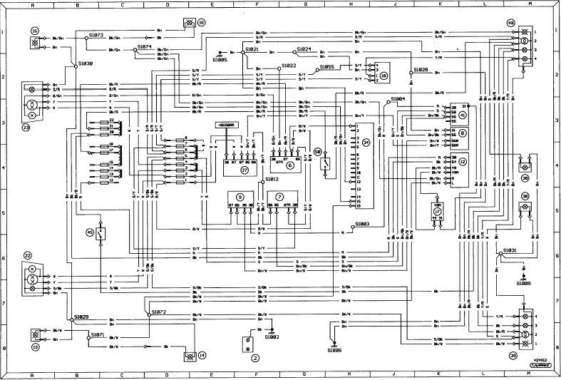
Diagram 2. Exterior lighting. P100 models from 1988 onwards
Diagram 3. Ancillary circuits and interior lighting. P100 model from 1988 onwards
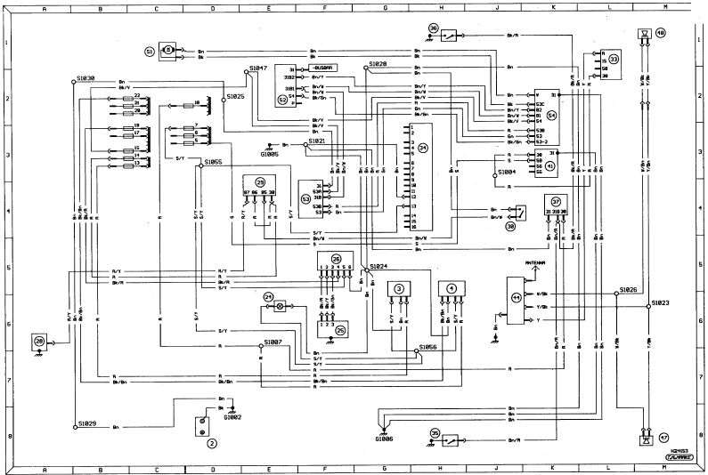
Diagram 3. Ancillary circuits and interior lighting. P100 model from 1988
onwards
See also:
General information and precautions
General information
The fuel system comprises a centrally
mounted fuel tank, electrically-operated fuel
pump and Bosch K-Jetronic or KE-Jetronic
continuous injection system according to
model. Th ...
Engine - removal leaving manual gearbox in vehicle
Warning: Vehicles equipped
with air conditioning:
Components of the air
conditioning system may
obstruct work being undertaken
on the engine and it is not always possible
to unbolt and move them ...
Idle speed control valve - removal and refitting
Note: A new gasket must be used when
refitting the valve.
2.0 litre SOHC models
1 Disconnect the battery negative lead.
2 Disconnect the idle speed control valve
wiring plug by releasing the reta ...
