Weber 2V carburettor automatic choke unit - removal, checking and refitting
XR3 models
Removal
1 Remove the air cleaner (Section 2).
2 Disconnect the electrical lead to the automatic choke.
3 Undo the three choke housing cover retaining screws, withdraw the cover and bimetal coil, followed by the internal heat shield.
4 Undo the six carburettor upper body retaining screws, hold the fast idle operating lever clear of the choke housing and lift off the upper body.
5 Undo the three screws securing the choke housing to the upper body, disconnect the link rod and remove the choke housing (see illustration).
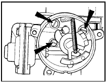
15.5 Weber 2V carburettor choke housing retaining screw locations - XR3
models
6 Undo the three screws and remove the vacuum pull-down housing cover, then withdraw the spring, diaphragm and operating rod assembly (see illustration).
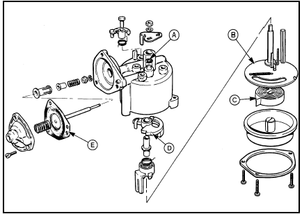
15.6 Exploded view of the Weber 2V carburettor automatic choke unit - XR3
models
A Housing O-ring
B Heat shield
C Bi-metal coil
D Fast idle cam
E Pull-down diaphragm
7 Extract the circlip on the end of the vacuum pull-down operating rod and slide off the rod components.
8 Make a note of the exact position of the choke mechanism return and tension springs then undo the shaft nut, withdraw the shaft from the choke housing and remove the linkages and cams.
Checking
9 Clean and inspect all the parts for wear,
damage, cracking, or distortion. Pay particular
attention to the condition of the pull-down
diaphragm and the choke housing O-ring
seal. Renew any parts as necessary.
Refitting
10 Reassemble the choke mechanism shaft,
linkages, cams and tension springs with
reference to illustration 15.6 and the notes
made during removal. Secure the shaft with
the retaining nut.
11 Assemble the components to the vacuum pull-down operating rod and secure with the circlip.
12 Locate the vacuum pull-down diaphragm and operating rod to the choke housing and with the diaphragm laying flat on the housing face refit the cover and secure with the three screws.
13 Place the O-ring seal on the choke housing, then connect the housing to the link rod.
14 Position the housing on the carburettor upper body and secure with the three screws.
15 Refit the upper body to the carburettor.
16 Before refitting the housing cover and bimetal coil, refer to Section 14 and adjust the vacuum pull-down and choke phasing, then fit the cover and bi-metal coil as described.
1.6 litre models - 1986 onwards
Removal
17 Remove the air cleaner as described in
Section 2.
18 Release any pressure in the cooling system by loosening the filler cap, then detach the water inlet and outlet hoses at the automatic choke unit. Clamp the hoses or position them with their ends facing upwards to minimise coolant leakage.
19 Disconnect the lead at the anti-run-on valve solenoid.
20 Disconnect the fuel supply and return hoses at the carburettor. If crimped type hose clips are used, cut them off and use screw type clips at reassembly.
21 Undo the six carburettor upper body retaining screws and remove the upper body.
Note that four of the screws are of the Torx type and a suitable key or socket bit will be needed for removal.
22 With the upper body removed, undo the three screws and remove the choke bi-metal coil housing followed by the internal heat shield.
23 Undo the three screws securing the choke housing to the upper body, disconnect the link rod and remove the choke housing (see illustration).
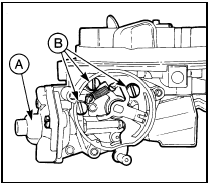
15.23 Weber 2V carburettor pull-down housing cover (A) and choke housing
retaining screws (B) - 1.6 litre models
24 Undo the three screws and remove the vacuum pull-down housing cover, then withdraw the spring, diaphragm and operating rod assembly.
25 Make a note of the exact position of the choke mechanism return and tension springs, then undo the nut and remove the connecting rod, levers and link from the choke housing (see illustration).
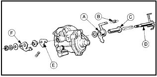
15.25 Exploded view of the Weber 2V carburettor automatic choke unit - 1.6
litre models
A Upper choke operating link
B Fast idle cam return spring
C Connecting rod sleeve
D Connecting rod and lever
E Pull-down link
F Actuating lever
Checking 26 Clean and inspect all the parts for wear, damage, cracking or distortion. Pay particular attention to the condition of the pull-down diaphragm and the choke housing O-ring seal. Renew any parts as necessary.
Refitting
27 Reassemble the choke mechanism
connecting rod, levers, link and springs with
reference to illustration 15.25 and the notes
made during removal. Secure the assembly
with the retaining nut.
28 Locate the vacuum pull-down diaphragm and operating rod in the choke housing. With the diaphragm lying flat on the housing face, refit the cover and secure with the three screws.
29 Locate the O-ring seal on the choke housing, then connect the housing to the link rod.
30 Position the housing on the carburettor upper body and secure with the three screws.
31 Refit the upper body to the carburettor.
32 Before refitting the bi-metal coil housing refer to Section 14 and adjust the vacuum pull-down, then fit the coil housing as described.
See also:
Speedometer cable - removal and refitting
Removal
1 On models fitted with a trip computer,
remove the speed sender unit.
2 Remove the instrument panel.
3 Pull the cable through the bulkhead into the
engine compartment, and where applicab ...
Fuel pressure regulator - removal and refitting
Caution: Refer to the
precautions in Section 1 before
proceeding.
2.0 litre SOHC models
1 Disconnect the battery negative lead.
2 Slowly loosen the fuel feed union to relieve
the pressure in the ...
Sump - removal and refitting
Note: A new gasket and new sump bolts must
be used when refitting, and suitable sealant will
be required (available from a Ford dealer). Note
that it is preferable to keep the engine upright
until ...
