Exhaust emission control system components - removal and refitting
Carburettor engines
Spark delay/sustain valve
Removal
1 Disconnect the vacuum lines at the valve
and remove the valve from the engine.
Refitting
2 When refitting a spark delay valve it must
be positioned with the black side (marked
CARB) towards the carburettor and the
coloured side (marked DIST) towards the
distributor. When refitting a spark sustain
valve the side marked VAC must be towards
the carburettor and the side marked DIST
towards the distributor.
Ported vacuum switch
Removal
3 Remove the filler cap from the expansion
tank to reduce pressure in the cooling system.
If the engine is hot, remove the cap slowly using a rag to prevent scalding.
4 Disconnect the vacuum lines and the water hoses, then unscrew the valve.
Refitting
5 When refitting the valve, note that the
vacuum line from the carburettor is connected
to the middle outlet on the PVS, the vacuum
line from the spark delay valve (where fitted) is
connected to the outlet nearest to the threaded
end of the PVS, and the vacuum line from the
spark sustain valve is connected to the outlet
furthest from the threaded end of the PVS.
6 Reconnect the water hoses and if necessary top-up the cooling system.
Fuel trap
Removal
7 Disconnect the vacuum lines and remove
the fuel trap from the engine.
Refitting
8 When refitting, make sure that the fuel trap
is positioned with the black side (marked
CARB) towards the carburettor and the white
side (marked DIST) towards the PVS (see
illustration).
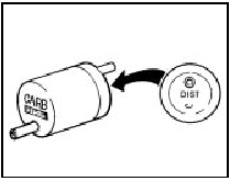
7.8 Fuel trap marked for direction of fitting
Central Fuel Injection (CFI)
engines
Catalytic converter
Removal
Note: Handle the catalyst with care. Any
sudden knocks can cause damage to the
internal substrates
9 Disconnect the battery negative lead.
10 Apply the handbrake, then jack up the front of the vehicle and support it securely on axle stands (see “Jacking and Vehicle Support”).
11 Remove the bolts from the exhaust downpipe-to-catalytic converter flanged joint.
12 Unscrew the nuts, and remove the clamp securing the rear of the catalytic converter to the exhaust system.
13 Unhook the catalytic converter from the rubber mountings, and carefully manipulate the converter from under the vehicle. If necessary, unhook the front end of the exhaust system from the rubber mountings to ease the procedure.
Refitting
14 Commence refitting by ensuring that the
mating faces of the catalytic converter,
downpipe, and exhaust system are clean.
15 Examine the mounting rubbers, and renew if necessary, noting that the rubbers used are of a special high temperature type due to the high operating temperature of the catalyst.
16 Loosely fit the catalytic converter in position, but do not tighten the fixings yet.
Use a new gasket at the converter-todownpipe flanged joint.
17 Carefully align the downpipe, converter and exhaust system, then tighten the fixings.
18 Lower the vehicle and reconnect the battery negative lead, then start the engine and check the exhaust system for leaks.
Heater Exhaust Gas Oxygen (HEGO)
sensor
19 Refer to Part C of this Chapter.
See also:
Boot lid lock (Saloon models) - removal and refitting
Removal
1 With the boot lid raised, remove the lock
barrel retaining clip.
2 Where applicable, disconnect the operating
lever from the central locking solenoid/motor,
then withdraw the lock barre ...
Handbrake cable - adjustment
Note: Where fitted, the adjuster locking pin
must be renewed on completion of
adjustment.
Conventional braking system
(except P100 models)
1 The handbrake cable is normally
self-adjusting in use ...
Fuel system (1.6 and 1.8 litre (R6A type) CVH) - depressurisation
Remember to depressurise the
fuel system before loosening any
connections.
Refer to the precautions in
Section 1 before proceeding. The fuel
system will remain pressurised after the
engine is sw ...
