Vacuum servo unit and linkage - removal and refitting
Removal
1 Refer to Section 12 and remove the master
cylinder.
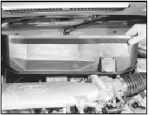
2 On fuel-injection models unclip and lift out the front section of the heater plenum chamber to provide access to the connecting linkage across the lower bulkhead (see illustration).

16.2 Heater plenum chamber removal
3 Working inside the vehicle, remove the spring clip which attaches the pushrod to the arm of the brake pedal.
4 Unscrew the nuts which hold the servo to its mounting bracket, also the servo support brace to the body.
5 Disconnect the valve hose from the servo.
6 Detach the linkage arm spring at the rear of the servo and then pull the servo forward until the servo operating rod can be unclipped from the linkage.
7 Remove the servo from the vehicle. It must be renewed if defective, no repair is possible.
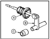
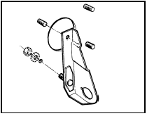
8 If necessary, the rest of the servo operating linkage can be removed from under the instrument panel once the covering and cowl side trim have been removed from above the brake pedal inside the vehicle. Unbolt the connecting link bracket from the driverís side (see illustrations).

16.8a Vacuum servo unit connecting linkage
A Grommet
B Connecting link
C Bush

16.8b Vacuum servo unit connecting link bracket on driverís side
Refitting 9 Refitting is the reverse sequence to removal. Refit the master cylinder as described in Section 12 and bleed the hydraulic system as described in Sections 11 or 23 as applicable.
See also:
Cylinder head - removal and refitting (engine removed)
Note: Up to early 1984, splined type cylinder
head bolts were used, and from early 1984,
size T55 Torx bolts were used. Torx type bolts
must always be renewed after slackening. The
two types of bo ...
Crankcase emission control filter renewal - CVH engines (Every
24 000 miles or 2 Years)
Carburettor and Central Fuel
Injection (CFI) engines
1 Where fitted, the crankcase ventilation filter
is located in the base of the air cleaner.
2 The filter can be renewed by pulling it out of
t ...
Specifications
General
System type:
1.1 litre OHV engines . . . . . . . . . . . . . . . . . . . . . . . . . . . . .
. . . . . . . . Mechanical contact breaker and coil
1.1 litre CVH engines up to 1986 . . . . . ...
