
Diagram 4a: 1984-86 KE-Jetronic fuel injection
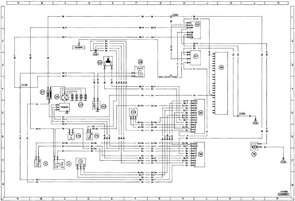
Diagram 4a: 1984-86 KE-Jetronic fuel injection For starting and charging
circuits see Diagram 1
See also:
Engine - reassembly
Note: Ensure that all necessary new oil seals
and gaskets have been obtained before
starting the reassembly procedure.
OHV engines
1 With everything clean, commence
reassembly by oiling the bores ...
Sunroof - removal, refitting and adjustment
Glass panel - removal and
refitting
1 Open the sunblind and remove the three
screws and clips shown (see illustration)
then slide the lower frame rearwards into the
roof.
39.1 Sunroof lower fr ...
Major body damage - repair
Where serious damage has occurred or
large areas need renewal due to neglect, it
means that completely new sections or panels
will need welding in, and this is best left to
professionals. If the d ...
