Mixture adjustment check (Every 6000 miles (10 000 km) or 6 months)
Caution: Refer to the precautions in Section 1, Chapter 4, Part A or B (as applicable), before proceeding.
Before carrying out any carburettor adjustments, ensure that the ignition timing and spark plug gaps are set as specified. To carry out the adjustments an accurate tachometer and an exhaust gas analyser (CO meter) will be required.
Ford VV carburettor
1 Ensure that the air cleaner is correctly fitted
and that all vacuum hoses and pipes are
securely connected and free from restrictions,
then run the engine until it is at normal
operating temperature.
2 Stop the engine, and connect a tachometer and an exhaust gas analyser in accordance with the manufacturer’s instructions.
3 Start the engine and run it at 3000 rpm for 30 seconds, ensuring that all electrical loads are switched off (headlamps, heater blower etc), then allow the engine to idle and check the idle speed and CO content. Note that the CO reading will initially rise, then fall and finally stabilise after between 5 and 25 seconds.
4 If the reading noted in paragraph 3 is not as specified, proceed as follows.
5 Using a thin screwdriver, remove the tamperproof seal from the mixture screw.
6 Run the engine at 3000 rpm for 30 seconds, then allow the engine to idle, and using a small screwdriver or a 4.0 mm Allen key, as applicable, adjust the mixture screw to give the specified CO content.
7 Checking and adjustment should be completed within 30 seconds of the meter readings stabilising. If this has not been possible, then repeat paragraph 6.
8 If necessary adjust the idle speed, then recheck the CO content.
9 On completion of the adjustments, stop the engine and disconnect the tachometer and exhaust gas analyser. Fit a new tamperproof seal to the mixture screw.
Weber 2V carburettor
Models without stepper motor
10 Proceed as described for the Ford VV
carburettor but note the following:
11 To remove the mixture screw tamperproof
seal, it will be necessary to drill the seal in
order to prise it from the mixture screw
housing. Alternatively a self-tapping screw
can be used to draw out the seal. If the
tamperproof seal is to be renewed, ensure
that a blue-coloured replacement seal is
fitted.
12 It is permissible to loosen the air cleaner securing screws to allow easier access to the carburettor adjustment screws, but ensure that all vacuum hoses and pipes are securely connected.
Models with stepper motor (ESC II
system)
13 If necessary, the mixture can be adjusted
as described for the Ford VV carburettor with
reference to paragraphs 11 and 12 of this
Section. Do not attempt to adjust the idle
speed on completion of mixture adjustment.
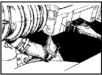
For adjustment screw location (see illustration).
16.13 Weber 2V carburettor idle mixture adjustment screw location (arrowed) -
2.0 litre models from 1985
Pierburg 2V carburettor 14 Proceed as described for the Ford VV carburettor.
Weber 2V TLD carburettor 15 Proceed as described for the Ford VV carburettor, noting the following points: 16 Ensure that the vacuum pipe and the camshaft cover breather hose are securely connected to the air cleaner and are free from restrictions.
17 When warming-up the engine, run the engine until the cooling fan cuts in.
18 If adjustment of the mixture (CO content) is required, the air cleaner must be removed for access to the adjustment screw, as follows.
19 Remove the air cleaner, and prise the tamperproof seal from the mixture screw.
20 Loosely refit the air cleaner, ensuring that the vacuum pipe and the camshaft cover breather hose are securely connected and free from restrictions (there is no need to secure the air cleaner in position).
21 On completion, fit a new tamperproof seal to the mixture screw (the service replacement plug is coloured blue), and refit the air cleaner assembly.
Fuel injection
2.0 litre SOHC models
22 The idle mixture can be checked and if
necessary adjusted as follows:
23 Run the engine until it is at normal
operating temperature.
24 Stop the engine and connect a tachometer and an exhaust gas analyser in accordance with the manufacturer’s instructions.
25 Start the engine and run it at 3000 rpm for 15 seconds, ensuring that all electrical loads (headlamps, heater blower etc) are switched off, then allow the engine to idle and check the CO content. Note that the CO reading will initially rise, then fall and finally stabilise.
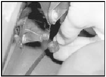
26 If adjustment is necessary, remove the tamperproof cap from the base of the airflow meter, and turn the mixture screw using a suitable Allen key to give the specified CO content (see illustration).
16.26 Adjusting the idle mixture - SOHC models
27 Checking and adjustment should be completed within 30 seconds of the meter readings stabilising. If this has not been possible, run the engine at 3000 rpm, for 15 seconds, then allow the engine to idle. Recheck the CO content and carry out further adjustment if necessary.
28 On completion of adjustment, stop the engine and disconnect the tachometer and exhaust gas analyser. Fit a new tamperproof cap to the mixture screw.
2.0 litre DOHC models
29 On models with a catalytic converter, the
mixture is controlled by the EEC IV module.
No manual adjustment is possible.
30 On models without a catalytic converter, the idle mixture can be adjusted as follows: 31 Run the engine until it is at normal operating temperature.
32 Stop the engine, and connect a tachometer and an exhaust gas analyser in accordance with the equipment manufacturer’s instructions.
33 Start the engine and run it at 3000 rpm for 15 seconds, ensuring that all electrical loads (headlamps, heater blower, etc) are switched off. Allow the engine to idle, and check the CO content. Note that the reading will initially rise, then fall and finally stabilise.
34 If adjustment is necessary, remove the cover from the mixture adjustment potentiometer (located at the rear right-hand side of the engine compartment, behind the MAP sensor), and turn the screw to give the specified CO content (see illustrations).
16.34a Remove the cover from the mixture adjustment potentiometer . . .
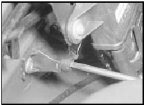
16.34b . . . to enable mixture adjustment - DOHC models
35 If adjustment does not produce a change in reading, the potentiometer may be at the extreme of its adjustment range. To centralise the potentiometer, turn the adjustment screw 20 turns clockwise followed by 10 turns anticlockwise, then repeat the adjustment procedure.
36 Checking and adjustment should be completed within 30 seconds of the meter readings stabilising. If this has not been possible, run the engine at 3000 rpm for 15 seconds, then allow the engine to idle. Recheck the CO content, and carry out further adjustments if necessary.
37 On completion of adjustment, stop the engine, and disconnect the tachometer and the exhaust gas analyser. Refit the cover to the adjustment screw.
See also:
Anti-theft alarm - location, removal and refitting
Note: The alarm system has a self-diagnosis
function, which allows a Ford dealer to carry
out fault diagnosis, using suitable specialist
equipment. In the event of a problem with the
alarm system, ...
Throttle Position Sensor (TPS) - removal and refitting
Removal
Note: During this procedure, ensure that the
sensor wiper is not rotated beyond its normal
operating arc
1 Disconnect the battery negative lead.
2 Disconnect the wiring plug from the sens ...
Inner gutter weatherstrip (Saloon, Hatchback and Estate models) - removal
and refitting
Removal
1 Open both the front and rear doors to
expose the relevant weatherstrip.
2 Carefully pull the weatherstrip from the
base of the front pillar, taking care to release
the flap which is stu ...
