Inlet manifold - removal and refitting
Caution: Refer to the precautions in Section 1 before proceeding.
Note: A tachometer and an exhaust gas analyser will be required to check the idle mixture on completion. A new gasket must be used when refitting the manifold.
2.0 litre SOHC models
1 Disconnect the battery negative lead.
2 Partially drain the cooling system.
3 Disconnect the crankcase ventilation hose from the air inlet hose. Disconnect the air inlet hose from the inlet manifold and the airflow meter.
4 Disconnect the HT lead from the coil, then remove the distributor cap and position the cap and HT leads clear of the inlet manifold assembly.
5 Unscrew the two securing bolts and remove the throttle cable bracket (see illustration).
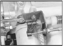
30.5 Unscrew the securing bolts and remove the throttle cable bracket
Disconnect the cable end from the throttle lever, and move the bracket to one side.
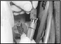
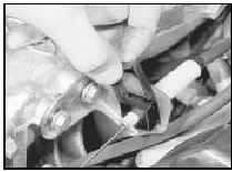
6 Disconnect the fuel injection harness wiring plugs at the bulkhead end of the manifold (see illustration).
30.6 Disconnecting a fuel injection harness wiring plug
7 Disconnect the oil pressure warning lamp switch wire from below the manifold.
8 Disconnect the fuel supply hose from the fuel rail. Loosen the union nut slowly to relieve the pressure in the fuel system, and be prepared for petrol spillage.
9 Disconnect the fuel return hose from the fuel pressure regulator. Be prepared for fuel spillage.
10 Disconnect the coolant hose and the brake servo vacuum hose from the inlet manifold.
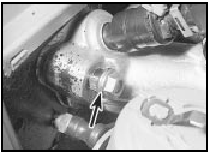
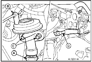
11 Unscrew the two securing nuts and remove the bracing strut which runs from the manifold to the right-hand side of the cylinder head (see illustration).
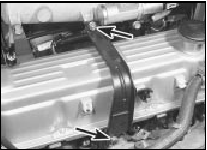
30.11 Unscrew the two securing nuts (arrowed) and remove the inlet manifold
bracing strut
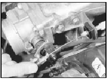
12 Unscrew the two bolts securing the lower manifold bracket to the left-hand side of the cylinder block (see illustration).
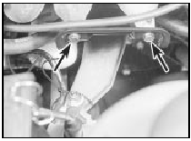
30.12 Lower inlet manifold bracket (arrowed)
13 Remove the four bolts and two nuts securing the inlet manifold to the cylinder head, and carefully withdraw the manifold. If the distributor obstructs removal, extract the front manifold stud by locking two nuts together and using them to unscrew the stud (see illustration).
30.13 Where necessary use two nuts locked together (arrowed) to remove the
front inlet manifold stud
Alternatively, the distributor can be removed, although this is not recommended unless absolutely essential.
Recover the gasket. Note that an earth strap may be located on one of the manifold securing bolts or studs; where applicable, note its location as an aid to refitting.
14 With the manifold removed, the various fuel injection system components can be separated from the manifold with reference to the relevant Sections of this Chapter.
15 Refitting is a reversal of removal, bearing in mind the following points.
16 Renew the gasket, and apply a bead of sealant at least 5.0 mm (0.2 in) wide around the central coolant aperture on both sides of the gasket. Ensure that all mating faces are clean.
17 Tighten the manifold securing nuts and bolts progressively to the specified torque, where applicable ensuring that the earth strap is in position.
18 Make sure that all hoses, cables, wires and leads are correctly reconnected. When reconnecting the air inlet hose, make sure that the hose clips are correctly aligned, see illustration, Section 15.
19 On completion, refill the cooling system, adjust the throttle cable and check and if necessary adjust the idle mixture.
2.0 litre DOHC models
Note: New fuel injector seals must be used on
refitting.
20 Disconnect the battery negative lead.
21 Partially drain the cooling system.
22 Disconnect the coolant hoses from the thermostat housing and the inlet manifold.
23 Disconnect the air inlet hose from the front of the inlet manifold.
24 Disconnect the breather hoses and the vacuum hoses from the inlet manifold noting their locations when disconnecting the brake servo vacuum hose.
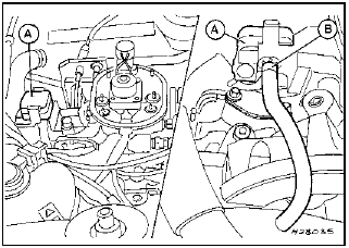
25 Disconnect the throttle cable from the throttle linkage (see illustrations).
30.25a Disconnect the throttle cable from the securing bracket . . .
30.25b . . . and the throttle linkage
26 Disconnect the HT leads from the spark plugs, noting their locations to aid refitting, and move them to one side.
27 Disconnect the wiring from the cooling fan switch, the engine coolant temperature sensor, and the temperature gauge sender.
28 Release the throttle position sensor wiring connector from the clip under the throttle body, and separate the two halves of the connector.
29 Remove the fuel injectors.
30 Check that all relevant wiring, hoses and pipes have been disconnected, to facilitate removal of the manifold.
31 Unscrew the ten bolts and two nuts securing the inlet manifold to the cylinder head, and carefully withdraw the manifold.
Recover the gasket.
32 Recover the two plastic spark plug spacers from the recesses in the cylinder head (see illustration).
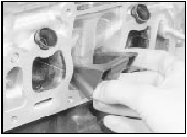
30.32 Removing a spark plug spacer from the cylinder head recess
33 If desired, the manifold can be dismantled with reference to the relevant paragraphs of this Chapter.
34 Refitting is a reversal of removal, bearing in mind the following points.
35 Ensure that the spark plug spacers are in position in the cylinder head recesses before refitting the manifold.
36 Renew all gaskets.
37 Tighten all manifold securing nuts and bolts progressively to the specified torque.
38 Make sure that all hoses, pipes and wires are securely reconnected in their original positions.
39 On completion, refill the cooling system.
Check the adjustment of the throttle cable and if necessary adjust the idle speed and mixture (as applicable).
1.6 and 1.8 litre (R6A type) CVH
models
40 Disconnect the battery negative lead.
41 Remove the air cleaner assembly.
42 Depressurise the fuel system and disconnect the fuel inlet pipe from the CFI unit.
43 Disconnect the fuel return pipe from the CFI unit. Be prepared for fuel spillage.
44 Disconnect the throttle cable from the linkage on the CFI unit.
45 Partially drain the cooling system.
46 Disconnect the coolant hoses from the thermostat housing and, where applicable, the CFI unit.
47 Disconnect the vacuum and breather hoses from the inlet manifold and the CFI unit, noting their locations.
48 Disconnect the wiring from the following components, according to engine type.
Air charge temperature sensor.
Throttle position sensor.
Fuel pressure regulator/injector.
Throttle valve control motor.
Engine coolant temperature sensor.
Cooling fan switch.
Temperature gauge sender.
49 Unbolt the dipstick tube from the inlet manifold, and withdraw the dipstick and dipstick tube from the cylinder block.
50 Make a final check to ensure that all relevant wires, hoses and pipes have been disconnected to facilitate removal of the manifold.
51 Unscrew the seven nuts, or six securing nuts and the single bolt, securing the inlet manifold to the cylinder head, then lift the manifold from the cylinder head. Recover the gasket.
52 If desired, the CFI unit can be removed from the inlet manifold.
53 If necessary, the thermostat and housing can be removed from the manifold.
54 Refitting is a reversal of removal, noting the following points.
55 Ensure that all mating faces are clean, and renew all gaskets.
56 Tighten the manifold nuts (and bolt, where applicable) progressively to the specified torque.
57 Make sure that all wires, hoses and pipes are reconnected as noted before removal.
58 Top-up the cooling system.
59 On completion, turn the ignition on and off five times to pressurise the system, and check for fuel leaks.
Exhaust gas recirculation valve (1.8 litre (R6A type) CVH) - removal and refitting
1 The EGR valve is located on the right-hand side of the engine, below the CFI unit.
2 Disconnect the battery negative lead.
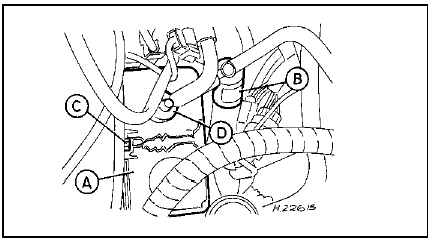
3 Disconnect the vacuum hose connecting the EGR valve to the electronic vacuum regulator (see illustration).
31.3 Exhaust gas recirculation valve attachments - 1.8 litre (R6A) CVH
A Metal tube-to-EGR valve retaining nut
B Vacuum hose
C EGR valve retaining bolts
D EGR valve metal tube location
4 Undo the nut securing the metal tube to the underside of the valve. Undo the two bolts, and remove the valve from the engine.
5 Refitting is a reversal of removal, but loosely fit the metal tube securing nut to the EGR valve before fitting the valve in position.
Tighten the nut securely on completion.
Exhaust pressure transducer (1.8 litre (R6A type) CVH) - removal and refitting
1 The EPT unit is located on the right-hand side of the engine, behind the CFI unit (see illustration).
32.1 Exhaust pressure transducer attachments - 1.8 litre (R6A) CVH
A Exhaust pressure transducer B Vacuum hose
2 Disconnect the battery negative lead.
3 Remove the air cleaner assembly.
4 Disconnect the EPT wiring plug, and slip the unit out of its mounting bracket.
5 Detach the vacuum hose, and remove the unit from the car.
6 Refitting is a reversal of removal.
Carbon canister (models with catalytic converter) - removal and refitting
2.0 litre DOHC models 1 Where fitted, the carbon canister is located on the right-hand side of the engine compartment, underneath the coolant expansion tank.
2 Disconnect the battery negative lead.
3 Pull the plastic pipe from the canister (the connector is a push-fit in the canister) (see illustration).
33.3 Carbon canister and purge solenoid locations - DOHC
A Carbon canister
B Purge solenoid
C Canister retaining bolt
D Pipe
4 Unscrew the securing bolt, and lift the canister from its location.
5 Refitting is a reversal of removal.
1.6 and 1.8 litre (R6A type) CVH
models
6 The carbon canister (where fitted) is located
on the right-hand side of the engine
compartment.
7 Proceed as detailed in paragraphs 2 to 5 inclusive.
See also:
Electric cooling fan - removal and refitting
CVH models
1 Disconnect the battery negative lead.
Unclip the wiring connector from the fan
motor then unscrew the retaining nuts and
washers. Withdraw the fan shroud and
cooling fan assembly (se ...
Modulator drivebelt (antilock braking system) - removal and
refitting
Note: Whenever an ABS modulator adjuster
bolt is slackened or removed, the bolt threads
should be lightly coated with grease to
prevent the possibility of bolt seizure. Take
care not to contaminat ...
Distributor cap and rotor arm (OHC models) - removal and refitting
SOHC models
1 Disconnect the battery negative lead.
2 Where applicable, unclip the screening can
from the top of the distributor and disconnect
the earth strap (see illustration).
13.2 Unclippi ...
