Pistons/connecting rods - removal and refitting
Removal
1 Remove the sump, as described in Section
8, and the cylinder head, as described in
Section 7.
2 Check that the connecting rod and cap have adjacent numbers at their big-end to indicate their position in the cylinder block (No 1 nearest timing cover end of engine) (see illustration).
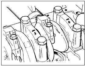
9.2 Connecting rod and main bearing identification numbers
3 Bring the first piston to the lowest point of its throw by turning the crankshaft pulley bolt and then check if there is a wear ring at the top of the bore. If there is, it should be removed using a scraper, but do not damage the cylinder bore.
4 Unscrew the big-end bolts and remove them.
5 Tap off the big-end cap. If the bearing shell is to be used again, make sure that it is retained with the cap. Note the two cap positioning roll pins.
6 Push the piston/rod out of the top of the block, again keeping the bearing shell with the rod if the shell is to be used again.
7 Repeat the removal operations on the remaining piston/rod assemblies.
8 Dismantling a piston/connecting rod is covered in Section 13.
Refitting
9 To refit a piston/rod assembly, have the
piston ring gaps staggered as shown (see
illustrations). Oil the rings and apply a piston
ring compressor. Compress the piston rings.
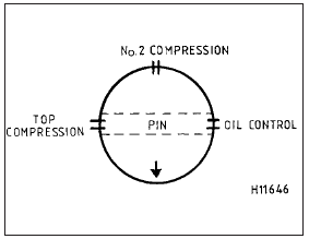
9.9a Piston ring end gap positioning diagram - all except 1.6 EFI engines
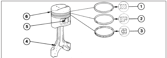
9.9b Piston ring profile and orientation - 1.6 EFI engine
1 Top compression ring
2 Second compression ring
3 Oil control rings
4 Oil squirt hole
5 Gudgeon pin
6 Piston ring grooves
10 Oil the cylinder bores.
11 Wipe clean the bearing shell seat in the connecting rod and insert the shell (see illustration).
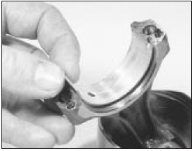
9.11 Fitting the bearing shell in the connecting rod
12 Insert the piston/rod assembly into the cylinder bore until the base of the piston ring compressor stands squarely on the top of the block.
13 Check that the directional arrow on the piston crown faces towards the timing cover end of the engine, then apply the wooden handle of a hammer to the piston crown.
Strike the head of the hammer sharply to drive the piston into the cylinder bore and release the ring compressor (see illustrations).
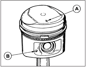
9.13a Arrow (A) or cast nipple (B) faces the timing belt end of the engine
when installed
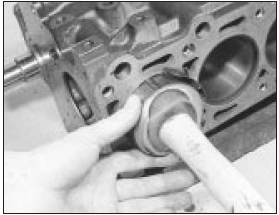
9.13b Installing a piston/connecting rod assembly
14 Oil the crankpin and draw the connecting rod down to engage with the crankshaft.
Make sure the bearing shell is still in position.
15 Wipe the bearing shell seat in the big-end cap clean and insert the bearing shell .
16 Lubricate the bearing shell with oil then fit the cap, aligning the numbers on the cap and the rod, screw in the bolts and tighten them to the specified torque setting (see illustrations).
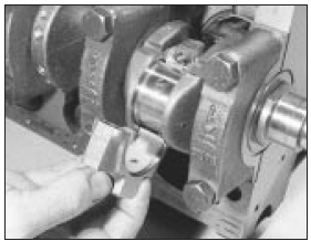
9.16a Fitting the big-end cap to the connecting rod
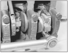
9.16b Tightening the big-end cap bolts to the specified torque
17 Repeat the operations on the remaining pistons/connecting rods.
18 Refit the sump (Section 8) and the cylinder head (Section 7). Refill the engine with oil and coolant.
See also:
Emission control system
Your vehicle is equipped with various emission control components and a
catalytic converter which will enable your vehicle to comply with
applicable exhaust emission standards. To make sure that the ...
Oil filler cap cleaning - OHVand HCS engines (Every 6000 miles
or 6 months)
1 Simply pull the oil filler cap from the rocker
cover and, where applicable, disconnect the
hose(s) from the cap.
2 Inspect the filler cap, and if necessary clean
the cap using clean petrol to re ...
Engine/manual gearbox assembly - reconnection and refitting
1 Reverse the procedure described in Section
11, noting the following points.
2 Before attempting to reconnect the engine
to the gearbox, check that the clutch friction
disc is centralised. This i ...
