Ignition timing (OHC models) - adjustment
Note: During production the ignition timing is accurately set using a microwave process, and sealant is applied to the distributor clamp bolt. Because the electronic components require no maintenance, checking the ignition timing does not constitute part of the routine maintenance schedule, and the procedure is therefore only necessary after removal and refitting of the distributor. A timing light will be required for this procedure. For details of ignition timing adjustment in order to operate vehicles on unleaded petrol refer to the appropriate Section of this Chapter.
All models except 2.0 litre DOHC
1 Before checking the ignition timing, the
following conditions must be met:
a) The engine must be at normal operating
temperature
b) Where applicable, the vacuum pipe to the
distributor vacuum unit or electronic
module (as applicable) must be
disconnected from the vacuum unit or
electronic module and plugged
c) The idle speed must be below 900 rpm
(isolate “idle speed adjustment” wire if
necessary)
d) Any earthed “octane adjustment” wires
must be temporarily isolated
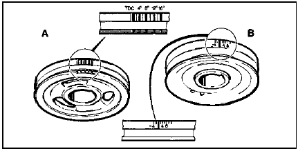
2 Wipe clean the crankshaft pulley timing
marks and the pointer on the crankshaft front
oil seal housing. Note that two alternative
types of pulley may be fitted (see
illustration).

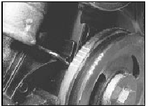
16.2a Highlighted timing marks - SOHC engine with cast crankshaft pulley
The desired timing values are given in the Specifications. If necessary, use white paint or chalk to highlight the relevant timing mark(s) (see illustration).

16.2b Crankshaft pulley timing marks - SOHC engine
A Cast pulley B Pressed steel pulley
3 Connect a stroboscope timing light to the No 1 cylinder HT lead, following the manufacturer’s instructions.
4 With the engine idling at normal operating temperature, point the timing light at the marks on the crankshaft pulley, and check that the appropriate timing mark appears stationary in line with the timing cover pointer.
Take care not to get the timing light leads, clothing etc tangled in the cooling fan blades or other moving parts of the engine.
5 If adjustment is necessary, stop the engine, slacken the distributor clamp bolt, and turn the distributor body slightly. Turn the distributor body clockwise to retard the ignition timing (move the timing closer to TDC) and anti-clockwise to advance the timing.
Note that the required distributor body movement will be half of the required crankshaft movement (ie an adjustment of 5 in ignition timing will require the distributor body to be turned 2º. Tighten the clamp bolt and re-check the timing.
6 On models with inductive discharge ignition systems, the mechanical and vacuum advance mechanisms can be checked as follows. On all other models, proceed to paragraph 10.
7 With the engine idling, timing light connected, and vacuum pipe disconnected as described in the preceding paragraphs, increase the engine speed to approximately 2000 rpm (if desired, connect a tachometer to the engine in accordance with the manufacturer”s instructions). Note the approximate distance which the relevant pulley mark moves out of alignment with the pointer.
8 Reconnect the vacuum pipe to the distributor or electronic module, as applicable, and repeat the procedure given in the previous paragraph, when for the same increase in engine speed, the alignment differential between the pulley mark and pointer should be greater than previously observed.
9 If the pulley mark does not appear to move during the first part of the check, a fault in the distributor mechanical advance mechanism is indicated. No increased movement of the mark during the second part of the check indicates a punctured diaphragm in the distributor vacuum unit, or a leak in the vacuum line.
10 On completion of the adjustments and checks, stop the engine and disconnect the timing light. Where applicable, reconnect the vacuum pipe, if not already done, and reconnect any “octane adjustment” and “idle speed adjustment” wires. Make a final check to ensure that the distributor clamp bolt is tight.
11 Finally, the idle speed and mixture should be checked and adjusted.
2.0 litre DOHC carburettor model 12 The ignition timing is controlled by the ESC II module, and no adjustment is possible.
2.0 litre DOHC fuel injection
model
13 The ignition timing is controlled by the
EEC IV module, and no adjustment is
possible.
See also:
Minor body damage - repair
Repair of minor scratches in
bodywork
If the scratch is very superficial, and does not
penetrate to the metal of the bodywork, repair is
very simple. Lightly rub the area of the scratch
with a pa ...
Ford VV carburettor automatic choke components - removal,
checking and refitting
Bi-metal housing
Note: A new gasket will be required on
refitting.
Removal
1 Disconnect the battery negative lead.
2 Remove the air cleaner as described in
Section 2.
3 Release any pressure in ...
Hydraulic pipes and hoses - renewal
Note: Before starting work, refer to the
warning at the beginning of Section 3
concerning the dangers of hydraulic fluid.
1 Always disconnect a flexible hose by
prising out the spring anchor clip ...
