Valve clearance adjustment - OHV and HCS engines (Every 12 000 miles or 12 months)
OHV engines 1 This operation should be carried out with the engine cold and the air cleaner and rocker cover removed.
2 Using a ring spanner or socket on the crankshaft pulley bolt, turn the crankshaft in a clockwise direction until No 1 piston is at TDC on its compression stroke. This can be verified by checking that the pulley and timing cover marks are in alignment and that the valves of No 4 cylinder are rocking. When the valves are rocking, this means that the slightest rotation of the crankshaft pulley in either direction will cause one rocker arm to move up and the other to move down. https://leaubk.com консультация по оформлению визы c5. Получение визы.
3 Numbering from the thermostat housing end of the cylinder head, the valves are identified as follows.
Valve No Cylinder No
1 Exhaust 1
2 Inlet 1
3 Exhaust 2
4 Inlet 2
5 Exhaust 3
6 Inlet 3
7 Exhaust 4
8 Inlet 4
4 Adjust the valve clearances by following the
sequence given in the following table. Turn
the crankshaft pulley 180є (half a turn) after
adjusting each pair:
Valves rocking Valves to adjust
7 and 8 1 (Exhaust), 2 (Inlet)
5 and 6 3 (Exhaust), 4 (Inlet)
1 and 2 7 (Exhaust), 8 (Inlet)
3 and 4 5 (Exhaust), 6 (Inlet)
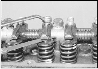
5 The clearances for the inlet and exhaust
valves are different (see Specifications). Use a
feeler blade of the appropriate thickness to
check each clearance between the end of the
valve stem and the rocker arm. The gauge
should be a stiff sliding fit. If it is not, turn the
adjuster bolt with a ring spanner. These bolts
are of stiff thread type and require no locking
nut. Turn the bolt clockwise to reduce the
clearance and anti-clockwise to increase it
(see illustration).

21.5 Valve clearance adjustment
6 Refit the air cleaner and rocker cover on completion of adjustment.
HCS engines
7 The procedure is as described previously
for OHV engines, but note that the valve
arrangement has been altered and is now as
shown below. Take care not to overtighten the
rocker cover bolts on refitting, as this can
result in leaks.
Valve No Cylinder No
1 Exhaust 1
2 Inlet 1
3 Exhaust 2
4 Inlet 2
5 Inlet 3
6 Exhaust 3
7 Inlet 4
8 Exhaust 4
See also:
Turbocharger-to-manifold nut check - RS Turbo models (Every 12
000 miles or 12 months)
Check the tightness of the turbocharger-toexhaust
manifold securing nuts using a torque
wrench. ...
Boot lid lock (Saloon models) - removal and refitting
Removal
1 With the boot lid raised, remove the lock
barrel retaining clip.
2 Where applicable, disconnect the operating
lever from the central locking solenoid/motor,
then withdraw the lock barre ...
Electronic modules - removal and refitting
Note: Refer to Section 1 for precautions to be
observed when working with electronic
modules.
1 Disconnect the battery negative lead.
All ESC modules except ESC
(early “Economy” models)
2 All mo ...
