Instrument panel - removal and refitting
Pre-1986 models
Removal
1 Disconnect the battery negative terminal.
2 Extract the screws and pull the instrument panel bezel from the panel. The two clips at the base of the bezel will release by the pulling action (see illustrations).
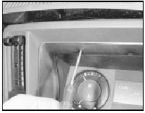
9.2a Extracting the instrument panel bezel screws - pre-1986 model
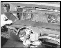
9.2b Removing the instrument panel bezel - pre-1986 model
3 Extract the two screws which hold the panel to the facia (see illustration).
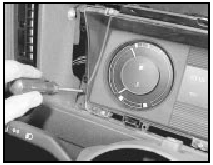
9.3 Removing an instrument panel retaining screw - pre-1986 model
4 Remove the dash under-trim panel, reach up and disconnect the cable from the speedometer by depressing the serrated plastic ring.
5 Gently pull the cluster forwards and to one side so that the wiring multi-plug can be disconnected. Withdraw the panel.
Refitting
6 Refitting is a reversal of removal.
1986 models onwards
Removal
7 Refer to Chapter 10 and remove the
steering wheel.
8 Extract the two screws and pull the instrument panel bezel from the panel. The two clips at the base will release by the pulling action (see illustration).
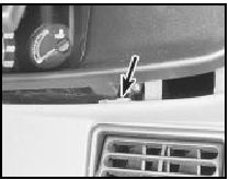
9.8 Bezel lower retaining clip (arrowed) - 1986 models onwards
9 Undo the four screws securing the panel to the facia (see illustrations).
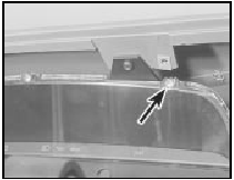
9.9a Instrument panel upper retaining screw (arrowed)
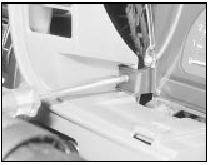
9.9b . . . and lower screw removal - 1986 models onwards
10 Pull the panel away from the facia and disconnect the wiring multi-plug and speedometer cable from the rear of the instrument panel. It may be necessary to feed the speedometer cable slack through the bulkhead from the engine compartment to facilitate removal. Withdraw the panel (see illustration).
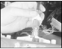
9.10 Disconnecting the speedometer cable
Refitting 11 Refitting is a reversal of removal.
See also:
Speedometer cable - removal and refitting
Removal
1 On models fitted with a trip computer,
remove the speed sender unit.
2 Remove the instrument panel.
3 Pull the cable through the bulkhead into the
engine compartment, and where applicab ...
Bumper - removal and refitting
Front bumper
Models up to 1987
1 Remove the radiator grille panel.
2 Disconnect the battery negative lead, then
disconnect the wiring plugs from the
indicators, and where applicable the
foglamps ...
Oil pump - removal and refitting
Note: New oil pump and oil pick-up tube
gaskets should be used when refitting.
Removal
1 With the engine removed, proceed as
follows.
2 Remove the timing belt, crankshaft
sprocket and thrustwash ...
