Engine/transmission - removal and separation
Note: Suitable lifting tackle will be required for this operation.
OHV engines
Removal
1 The engine is removed complete with the
transmission in a downward direction and then
withdrawn from under the front of the car.
2 Disconnect the battery negative lead.
3 Place the transmission in fourth gear on fourspeed versions, or reverse gear on the fivespeed unit to aid adjustment of the gearchange linkage when refitting. On models produced from February 1987 onwards, place the transmission in second gear on four-speed versions, or fourth gear on five-speed versions.
4 Remove the bonnet (Chapter 11).
5 Remove the air cleaner (Chapter 4, Part A).
6 Drain the cooling system (Chapter 1).
7 Disconnect both the radiator hoses and the expansion tank hose at the thermostat housing.
8 Disconnect the heater hoses from the stub on the lateral coolant pipe, automatic choke housing or inlet manifold as applicable (see illustration).
11.8 Heater hose attachments at lateral coolant pipe (A) and choke housing
(B)
9 Disconnect the choke cable (where fitted) and the throttle cable from the carburettor throttle lever. Unbolt the cable support bracket and tie the cable assembly to one side of the engine compartment.
10 Disconnect the fuel pipe from the fuel pump and plug the pipe.
11 On vehicles equipped with powerassisted brakes, disconnect the vacuum pipe from the inlet manifold.
12 Disconnect the leads from the following
electrical components:
a) Alternator and electric fan temperature
switch.
b) Oil pressure sender.
c) Coolant temperature sender.
d) Reversing lamp switch.
e) Anti-run on solenoid valve.
13 Disconnect the HT and LT (distributor) wires from the coil terminals.
14 Unscrew the speedometer drive cable from the transmission and release the breather hose.
15 Disconnect the clutch cable from the release lever and from its transmission support.
16 Unbolt and remove the hot air box from the exhaust manifold.
17 Disconnect the exhaust downpipe from the manifold by extracting the two flange bolts. Support the exhaust pipe to avoid straining it.
18 The vehicle should now be jacked up and safety stands fitted to provide sufficient clearance beneath it to be able to remove the engine/transmission from below. A distance of 686 mm (27.0 in) is recommended between the floor and the bottom edge of the front panel.
19 Disconnect the exhaust system from its flexible mountings and remove the system complete.
20 Disconnect the starter motor leads and the engine earth strap.
21 Disconnect the gearchange rod from the transmission selector shaft by releasing the clamp bolt and withdrawing the rod. Tie the rod to the stabiliser and then where fitted, unhook the tension spring.
22 Unscrew the single bolt and disconnect the stabiliser from the transmission housing, noting the washer fitted between the stabiliser trunnion and the transmission (see illustration).
11.22 Gearchange rod and stabiliser disconnection points - washer fitted
behind stabiliser arrowed
23 Remove the driveshafts from the transmission using the procedure described in the manual transmission removal procedure in Chapter 7, Part A. Note that on pre-1986 models equipped with an anti-roll bar the right-hand mounting clamp should also be undone and the bar lowered together with the suspension arms.
24 Connect a suitable hoist to the engine using chains and brackets (see illustration).
11.24 Typical lifting gear connection to engine
25 Just take the weight of the engine/transmission assembly so that the tension is relieved from the mountings.
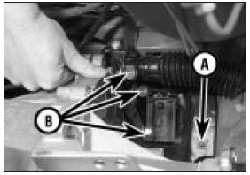
26 Unbolt the rear right-hand engine mounting (complete with coolant hose support on early models) from the side member and from the inner wing panel (see illustration).
11.26 Engine right-hand mounting attachment at side member (A) and inner wing
panel (B)
27 On pre-1986 models unbolt the front and rear transmission mountings from their brackets, and remove the front mounting and anti-roll bar support plates from the body on both sides (see illustration).
11.27 Remove the anti-roll bar support plates on both sides - pre-1986 models
28 On 1986 models onwards undo the nuts and bolts securing the transmission support crossmember to the body (see illustrations).
The crossmember is removed with the engine/transmission assembly.
11.28a Transmission support crossmember front mounting bolts (A) and
anti-roll bar support plate bolts (B) - 1986 models onwards
11.28b Transmission support crossmember rear mounting bolts -
1986 models onwards
29 Carefully lower the engine/transmission and withdraw it from under the car.
Separation
30 Unscrew and remove the starter motor
bolts and remove the starter.
31 Unbolt and remove the clutch cover plate from the lower part of the clutch bellhousing.
32 Unscrew and remove the bolts from the clutch bellhousing-to-engine mating flange.
33 Withdraw the transmission from the engine. Support its weight so that the clutch assembly is not distorted while the input shaft is still in engagement with the splined hub of the clutch driven plate.
HCS engines
Removal
34 The engine can be lifted from the engine
bay provided the radiator and certain other
ancillary components are removed first to give
room for manoeuvring. These are detailed in
the removal procedure.
35 Before commencing work it will be necessary to make up two lifting eyes from 1⁄4” mild steel bar, approximately 3” long and 11⁄2” wide, with two 1⁄2” holes drilled in them (see illustration).
11.35 A locally made-up lifting eye - HCS engine
36 Remove the bonnet (Chapter 11).
37 Disconnect the battery negative lead.
38 Remove the air cleaner (Chapter 4, Part A).
39 Drain the engine oil (Chapter 1).
40 Drain the coolant (Chapter 1).
41 Remove the radiator (Chapter 3) (see illustrations).
11.41a Radiator lower mounting bolt . . .
11.41b . . . and upper locating peg - HCS engine
11.41c Lifting out the radiator - HCS engine
42 Disconnect the heater hoses from the inlet manifold and the water pump.
43 Disconnect the lead at the anti-run-on valve solenoid on the carburettor.
44 Disconnect the throttle cable (Chapter 4, Part A).
45 Disconnect the choke cable (Chapter 4, Part A).
46 Disconnect the fuel inlet (blue clip) and outlet (green clip) pipes from the fuel pump (see Chapter 4, Part A).
47 Disconnect the brake servo vacuum hose from the inlet manifold. On later models depress the flanged collar towards the manifold, and pull out the hose (see illustration). Do not pull the hose at an angle, or use excessive force, or the hose may lock in position.
11.47 Disconnecting the brake vacuum servo hose - HCS engine
48 Disconnect the earth lead from the inlet manifold.
49 Disconnect the following electrical
connections:
a) Cooling fan thermal switch on thermostat
housing (see illustration).
11.49a Disconnecting the cooling fan thermal switch . . .
b) Coolant temperature sender (see illustration).
11.49b . . . and coolant temperature sender - HCS engine
c) Alternator.
d) Ignition (DIS) coil (Chapter 5, Part B).
e) Oil pressure switch.
f) Engine coolant temperature sensor (Chapter 5, Part B).
g) Engine speed sensor (Chapter 5, Part B).
h) Reversing light switch (Chapter 7, Part A).
I) Transmission housing earth lead.
50 Disconnect the speedometer cable (see illustration).
11.50 Disconnecting the speedometer cable - HCS engine
51 Disconnect the exhaust downpipe from the exhaust manifold flange. The nuts are easier to reach from underneath the vehicle.
Once undone, support the exhaust on wire.
52 Disconnect the starter motor and engine earth lead which is under one of the starter motor bolts (Chapter 5, Part A).
53 Remove the starter lead support bracket from the transmission housing.
54 Disconnect the gearchange mechanism (Chapter 7, Part A).
55 Remove the driveshafts (Chapter 8). Note: On removal of the driveshafts, push a length of wooden dowel into the hole vacated by the driveshaft in the transmission housing to prevent the sun gears of the differential becoming misaligned. A piece of broom handle is ideal, but will have to be turned down somewhat.
56 Support the right-hand side of the engine on a trolley jack; just take the weight of the engine.
57 Remove the right-hand engine mounting by undoing the top nut on the wing panel, removing the bolt accessible from inside the wheelarch, and the three bolts securing the mounting bracket to the engine (see illustrations).
11.57a Right-hand engine mounting nuts/bolts (arrowed) - HCS engine
11.57b One bolt (arrowed) is accessible from within the wheelarch - HCS
engine
58 Once removed, undo the Torx headed bolt securing the mounting to the bracket (see illustration).
11.58 Torx headed bolt (arrowed) securing the mounting to the bracket - HCS
engine
59 Refit the bracket to the cylinder block and bolt one of the made-up lifting eyes to the bracket using one of the spare bolts (see illustration).
11.59 Lifting eye (arrowed) bolted to righthand mounting position on cylinder
block . . .
60 Fit the other lifting eye to the transmission housing (see illustration).
11.60 . . . and on transmission housing - HCS engine
61 Secure suitable lifting gear to the engine and just begin to take the weight. Note: If the carburettor is likely to be damaged because of the angle of the lifting sling/chain, remove the carburettor as described in Chapter 4, Part A.
62 Remove the alternator (Chapter 5, Part A) to give more room for manoeuvring the engine out.
63 Pull the transmission breather hose from inside the wing panel.
64 Remove the nut from the left-hand front engine mounting.
65 Remove the nut from the left-hand rear mounting. Remove the nuts securing the mounting bracket to the transmission housing and remove the bracket (see illustrations).
11.65a Mounting nut location (A) and bracket-to-transmission housing nuts (B)
- HCS engine
11.65b Removing the mounting bracket - HCS engine
66 Commence lifting the engine slowly, checking all round that everything has been disconnected and that the engine does not foul other components as it is lifted. Swing the engine and tilt it as necessary to clear obstacles (see illustrations).
11.66a Lifting the engine and transmission upwards . . .
11.66b . . . and out of the engine compartment
67 Once out of the engine bay, swing the engine clear and lower it onto a suitable work surface.
Separation
68 Proceed as described previously in this
Section for OHV engines
See also:
CVH engines
CVH (Compound Valve angle, Hemispherical combustion chambers)
engines are of four cylinder in-line overhead camshaft type, mounted
transversely, together with the transmission, at the front of the ...
Heater unit - overhaul
1 With the heater unit removed from the
vehicle, remove the two securing screws and
withdraw the heater matrix from the casing
(see illustrations).
19.1a Remove the securing screws . . .
19.1 ...
Pistons/connecting rods - removal and refitting
Removal
1 Remove the sump, as described in Section
8, and the cylinder head, as described in
Section 7.
2 Check that the connecting rod and cap
have adjacent numbers at their big-end to
indicate ...
