Cylinder head and pistons - decarbonising
OHV engines 1 With the cylinder head removed (Section 4), the carbon deposits should be removed from the combustion spaces using a scraper and a wire brush fitted into an electric drill. Take care not to damage the valve heads, otherwise no special precautions need be taken as the cylinder head is of cast iron construction.
2 Where a more thorough job is to be carried out, the cylinder head should be dismantled (Section 13), so that the valves may be ground in and the ports and combustion spaces cleaned, brushed and blown out after the manifolds have been removed.
3 Before grinding in a valve, remove the carbon and deposits completely from its head and stem. With an inlet valve, this is usually quite easy, simply scraping off the soft carbon with a blunt knife and finishing with a wire brush. With an exhaust valve the deposits are much harder and those on the head may need a rub on coarse emery cloth to remove them.
4 Ensure that the valve heads are really clean, otherwise the suction cup of the grinding tool will not stick during the grinding-in operations.
5 Before starting to grind in a valve, support the cylinder head so that there is sufficient clearance under for the valve stem to project fully without being obstructed.
6 Take the first valve and apply a little coarse grinding paste to the bevelled edge of the valve head. Insert the valve into its guide and apply the suction grinding tool to its head.
Rotate the tool between the palms of the hands in a back-and-forth rotary movement until the gritty action of the grinding-in process disappears. Repeat the operation with fine paste and then wipe away all traces of grinding paste and examine the seat and bevelled edge of the valve. A matt silver mating band should be observed on both components, without any sign of black spots.
If some spots do remain, repeat the grindingin- process until they have disappeared. A drop or two of paraffin applied to the contact surfaces will increase the speed of grindingin, but do not allow any paste to run down into the valve guide. On completion, wipe away every trace of grinding paste using a paraffinmoistened cloth.
7 Repeat the operations on the remaining valves, taking care not to mix up their originally fitted sequence.
8 The valves are refitted as described in Section 13.
9 An important part of the decarbonising operation is to remove the carbon deposits from the piston crowns. To do this, turn the crankshaft so that two pistons are at the top of their stroke and press some grease between these pistons and the cylinder walls.
This will prevent carbon particles falling down into the piston ring grooves. Stuff rags into the other two bores.
10 Cover the oilways and coolant passages with masking tape and then using a blunt scraper remove all the carbon from the piston crowns. Take care not to score the soft alloy of the crown or the surface of the cylinder bore.
11 Rotate the crankshaft to bring the other two pistons to TDC and repeat the operations.
12 Wipe away the circle of grease and carbon from the cylinder bores.
13 Clean the top surface of the cylinder block by careful scraping.
HCS engines
14 The procedure is as described previously
in this Section for OHV engines, noting the
following.
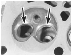
a) When cleaning out the swirl ports, great care must be exercised not to damage the valve seats, especially if using power tools (see illustration).

14.14a View of the swirl chamber in the cylinder head showing the valve seats
(arrowed) - HCS engine
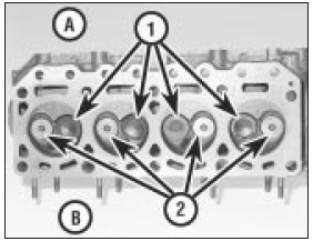
b) The valve arrangement is different, being of mirror effect, where the inlet valves for number 2 and 3 cylinders are next to each other (see illustration).

14.14b View of the cylinder head with valves fitted - HCS engine
A Inlet side
B Exhaust side
1 Inlet valves
2 Exhaust valves
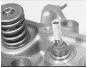
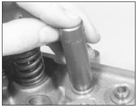
c) When refitting the valve stem oil seals, tape the end of the stem to prevent damage to the seal as it is fitted, and use a long reach socket or length of tube to push the seals fully down (see illustrations). Remove the tape on completion.

14.14c Tape the end of the valve stem before fitting the valve stem seal -
HCS engine
d) The valve seats cannot be re-worked using conventional tools.

14.14d Using a long reach socket to push the seal fully home - HCS engine
See also:
Engine/automatic transmission assembly - removal and separation
Note: A suitable hoist and lifting tackle will be
required for this operation. Any suspected
faults in the automatic transmission should be
referred to a Ford dealer or automatic
transmission spec ...
Throttle Position Sensor (TPS) - removal and refitting
Removal
1 Disconnect the battery negative lead.
2 Unclip and disconnect the sensor wiring
plug.
3 Remove the two securing screws, and
withdraw the sensor from the throttle valve
shaft (see illus ...
Road test (Every 12 000 miles or 12 months)
Instruments and electrical
equipment
1 Check the operation of all instruments and
electrical equipment.
2 Make sure that all instruments read
correctly, and switch on all electrical
equipment in ...
