Timing belt and sprockets - removal and refitting
Note: Refer to the warning in Section 8 before proceeding. On models from mid-1985 (without a timing belt tensioner spring) the belt tension should be checked using Ford special tool No 21-113 after refitting. On models up to mid-1985 (with a tensioner spring), a suitable splined socket will be required for the tensioner spring bolt. A suitable puller may be required to remove the sprockets.
Removal
1 If the engine is in the vehicle, carry out the
following operations:
a) Disconnect the battery negative lead
b) Remove the thermo-viscous cooling fan
c) Remove the coolant
pump/alternator/power-steering pump
drivebelt(s)
d) For improved access, remove the radiator
and disconnect the radiator top hose from
the thermostat housing
2 Unscrew the three securing bolts and
washers and withdraw the timing cover. Note
the position of the fourth bolt above the
crankshaft pulley which can be left in place.
3 Using a socket on the crankshaft pulley bolt, turn the engine clockwise until the TDC (top dead centre) mark on the crankshaft pulley is aligned with the pointer on the crankshaft front oil seal housing (see illustration 16.2a of Chapter 5) and the pointer on the camshaft sprocket backplate is aligned with the indentation on the cylinder head (see illustration).
19.3 TDC pointer on camshaft sprocket backplate aligned with indentation on
cylinder head
4 On models up to mid-1985 (with a tensioner spring), loosen the timing belt tensioner spring bolt using the special splined socket (see illustration),
19.4 Loosening the timing belt tensioner spring bolt using a splined socket -
models up to mid-1985
then loosen the tensioner pivot bolt. If necessary for improved access, remove the thermostat housing. Press the tensioner against the spring tension and tighten the pivot bolt to retain the tensioner in the released position.
5 On models from mid-1985 (without a tensioner spring), loosen the timing belt tensioner bolts (see illustration) and move the tensioner away from the belt. If necessary to improve access, remove the thermostat housing.
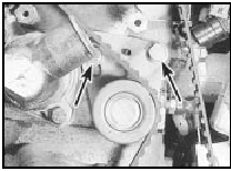
19.5 Timing belt tensioner bolts (arrowed) - models from mid-1985
6 Mark the running direction of the belt if it is to be re-used, then slip it off the camshaft sprocket.
7 Slacken the crankshaft pulley bolt. Prevent the crankshaft from turning by engaging top gear (manual gearbox only) and having an assistant apply the brake pedal hard, or by removing the starter motor and jamming the ring gear teeth with a lever. Alternatively, if the pulley has peripheral bolt holes, screw in a couple of bolts and use a lever between them to jam it. Do not allow the crankshaft to turn very far, or piston/valve contact may occur.
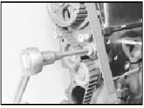
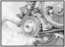
8 Remove the bolt and washer and withdraw the pulley. If the pulley will not come off easily, refit the bolt part way and use a puller (see illustration).
19.8 Using a puller to remove a pressed type crankshaft pulley
A puller will almost certainly be required on fuel-injection models.
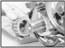
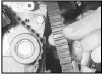
9 Remove the guide washer from in front of the crankshaft sprocket, then remove the timing belt (see illustration).
19.9 Removing the guide washer from the crankshaft
Do not kink it or
get oil on it if it is to be re-used.
10 If desired, the sprocket can be removed as follows, otherwise proceed to paragraph 21.
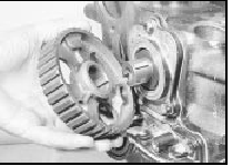
11 Remove the crankshaft sprocket, refitting the bolt part way and using a puller if necessary (see illustration).
19.11 Removing the crankshaft sprocket
12 Unscrew the auxiliary shaft sprocket bolt while holding the sprocket stationary with a screwdriver inserted through one of the holes.
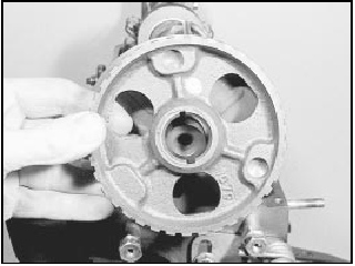
13 Remove the auxiliary shaft sprocket, refitting the bolt part way and using a puller if necessary (see illustration).
19.13 Removing the auxiliary shaft sprocket
14 Hold the camshaft sprocket stationary using a home-made tool similar to that shown (in illustration 18.17 in Part C of this Chapter) with two bolts engaged in the sprocket holes, and unscrew the bolt and washer.
Alternatively, remove the camshaft cover and hold the camshaft using a spanner on the boss behind the No 6 valve cam.
15 Remove the camshaft sprocket, refitting the bolt part way and using a puller if necessary, then remove the backplate, noting which way round it is fitted (see illustrations).
19.15a Removing the camshaft sprocket . . .
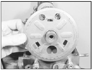
19.15b . . . and backplate
16 If desired, the camshaft oil seal can be removed using self-tapping screws and a pair of grips. A new seal can be fitted using a suitable tube drift to press it into place.
Lubricate the seal lips with clean engine oil before installation.
Refitting
17 Refit the sprockets as follows.
18 Fit the camshaft sprocket backplate, as noted during removal, then fit the sprocket.
Insert the bolt, hold the camshaft or sprocket as during removal, and tighten the bolt to the specified torque. Where applicable, refit the camshaft cover.
19 Fit the auxiliary shaft sprocket with the ribs towards the engine. Fit the sprocket bolt and tighten it to the specified torque, counterholding the sprocket with a bar through one of the holes.
20 Fit the crankshaft sprocket, chamfered side inwards.
21 Fit the timing belt over the crankshaft sprocket, but do not engage it with the other sprockets yet. Be careful not to kink the belt.
If the old belt is being refitted, observe the previously noted running direction.
22 Refit the guide washer and the crankshaft pulley. Fit the bolt and washer and tighten just enough to seat the pulley, being careful not to turn the crankshaft.
23 Make sure that the TDC pointer on the camshaft sprocket backplate is still aligned with the indentation on the cylinder head.
24 Make sure that the TDC mark on the crankshaft pulley is still aligned with the pointer on the oil seal housing. If necessary, turn the crankshaft by the shortest possible route to align the marks.
25 If the distributor is fitted, turn the auxiliary shaft sprocket so that the rotor arm points to the No 1 HT segment position in the distributor cap.
26 Fit the timing belt over the sprockets and round the tensioner.
27 On models up to mid-1985 (with a tensioner spring), slacken the pivot bolt, and allow the tensioner roller to rest against the belt. Using a socket on the crankshaft pulley bolt, turn the crankshaft through two complete revolutions in a clockwise direction, to bring No 1 cylinder back to TDC. Tighten the tensioner pivot bolt and then the spring bolt to the specified torque. Do not turn the crankshaft anti-clockwise with the belt tensioner released. Proceed to paragraph 33.
28 On models from mid-1985 (without a tensioner spring), move the tensioner to tension the belt roughly and nip up the tensioner bolts. Using a socket on the crankshaft pulley bolt, turn the crankshaft through two complete revolutions in a clockwise direction (to bring No 1 cylinder back to TDC), then turn the crankshaft 60º anti-clockwise (No 1 cylinder at 60º BTDC) (see illustration).
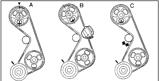
19.28 Timing belt tension checking sequence - models from mid-1985
A No 1 cylinder at TDC B No 1 cylinder at 60° BTDC for checking C Return No 1 cylinder to TDC for adjustment
29 The belt tension should now be checked
by applying Ford tension gauge, tool No 21-
113 to the longest belt run. Desired gauge
readings are:
Used belt - 4 to 5
New belt - 10 to 11
If the tension gauge is not available, a rough
guide is that the belt tension is correct when
the belt can be twisted 90º in the middle of the
longest run with the fingers, using moderate
pressure (see illustration).
19.29 Twisting the timing belt to assess its tension
In this case, the
vehicle should be taken to a Ford dealer so
that the belt tension can be checked using the
special gauge at the earliest opportunity.
30 If adjustment of belt tension is necessary, turn the crankshaft clockwise to bring No 1 cylinder to TDC, then slacken the tensioner bolts and move the tensioner to increase or decrease the belt tension. Tighten the tensioner bolts to the specified torque.
31 Turn the crankshaft 90º clockwise past TDC, then anti-clockwise back to the 60º BTDC position (No 1 cylinder at 60º BTDC).
Check the belt tension again.
32 Repeat the procedure given in paragraphs 30 and 31 until the belt tension is correct.
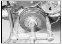
33 Tighten the crankshaft pulley bolt to the specified torque, preventing the crankshaft from turning as described in paragraph 7 (see illustration).
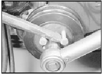
19.33 Holding a pressed type crankshaft pulley with two bolts and a lever
while tightening the bolt
34 Refit the timing cover and tighten its bolts.
35 If the engine is in the vehicle, reverse the operations described in paragraph 1.
36 When the engine is next started, check the ignition timing is correct.
See also:
Hydraulic system - bleeding (conventional braking system)
Note: On cars equipped with the Anti-lock
Braking System, refer to Section 23.
Warning: Hydraulic fluid is
poisonous; wash off immediately
and thoroughly in the case of skin
contact, and seek imm ...
Tailgate (Hatchback and Estate models) - removal and refitting
Note: On Hatchback models made before
1990 with an integral heated rear
window/radio aerial, note that the radio aerial
lead is routed through different openings to
that of other models in the rea ...
Trip computer components - removal and refitting
1 Disconnect the battery negative lead
Computer module
2 Remove the single screw from the top edge
of the facia panel in which the module is
housed, then withdraw the facia panel.
3 Remove the fo ...
