Engine - removal leaving manual gearbox in vehicle
Note: A suitable hoist and lifting tackle will be required for this operation.
1.8 litre (R2A type)
1 Disconnect the battery negative lead.
2 Remove the bonnet.
3 Remove the air cleaner.
4 Disconnect the cooling fan wiring plug, then unscrew the retaining nuts and washers and withdraw the fan shroud and cooling fan assembly.
5 Drain the cooling system.
6 Disconnect the coolant hoses from the coolant pump elbow, and detach the heater hose from the clip on the front of the timing cover.
7 Disconnect the upper radiator hose and the expansion tank hose from the thermostat housing (see illustration).
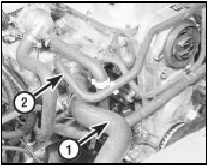
8.7 Disconnect the upper radiator hose (1) and the expansion tank hose (2)
from the thermostat housing - 1.8 litre (R2A)
8 Disconnect the heater hose from the automatic choke.
9 Disconnect the brake servo vacuum hose from the inlet manifold (see illustration).
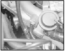
8.9 Disconnecting the brake servo vacuum hose from the inlet manifold - 1.8
litre (R2A)
10 Disconnect the throttle damper solenoid vacuum pipes (noting their locations) from the throttle damper and the carburettor “T”-piece connector.
11 Disconnect the engine management module vacuum pipe from the inlet manifold.
12 Disconnect the fuel hoses from the carburettor and fuel pump, and plug the ends of the hoses to minimise petrol spillage. Take adequate fire precautions.
13 Disconnect the throttle cable.
14 Disconnect the HT leads from the coil and spark plugs, unclip the leads from the camshaft cover, and remove the distributor cap, rotor arm and housing.
15 Disconnect the wiring from the following
components:
Alternator
Starter motor
Oil pressure warning lamp switch
Temperature gauge sender
Engine coolant temperature sensor
Automatic choke
Cooling fan switch
Crankshaft speed/position sensor
Engine earth strap to battery tray
16 Unscrew and remove the top engine-togearbox
bolts which are accessible from the
engine compartment.
17 Apply the handbrake (if not already done), jack up the front of the vehicle and support on axle stands (see “Jacking and Vehicle Support”).
18 Drain the engine oil into a container.
19 Remove the starter motor.
20 Remove the exhaust downpipe.
21 Unscrew the two nuts securing the engine mountings to the crossmember. Recover the washers.
22 Unscrew and remove the remaining engine-to-gearbox bolts, noting the location of the earth strap (see illustration),
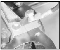
8.22a Earth strap location under engine-togearbox bolt - 1.8 litre (R2A)
and remove the two bolts from the engine adapter plate (see illustration).
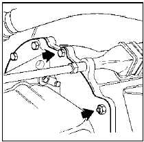
8.22b Remove the two bolts (arrowed) from the engine adapter plate - 1.8
litre (R2A)
23 Working inside the vehicle, place a wooden block under the clutch pedal to raise it fully against its stop which will hold the automatic adjuster pawl clear of the toothed quadrant.
24 Disconnect the clutch cable from the release arm, and pass the cable through the bellhousing. Remove the clip securing the clutch cable to the right-hand engine mounting bracket. Note the cable routing for use when refitting.
25 Lower the vehicle to the ground, and support the gearbox with a trolley jack using a block of wood between the jack and the gearbox to spread the load.
26 Make a final check to ensure that all relevant wires, pipes and hoses have been disconnected to facilitate engine removal.
27 Attach a suitable hoist to the engine lifting brackets located at the front and rear of the cylinder head, and carefully take the weight of the engine. The engine should be supported horizontally, ie do not allow it to tilt front to rear.
28 Raise the engine until the engine mounting studs are clear of the crossmember, then pull the engine forwards to disconnect it from the gearbox. Ensure that the gearbox is adequately supported, and take care not to strain the gearbox input shaft. It may be necessary to rock the engine a little to release it from the gearbox.
29 Once clear of the gearbox, lift the engine from the vehicle, taking care not to damage the radiator fins (see illustration).
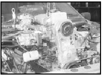
8.29 Lifting the engine from the vehicle - 1.8 litre (R2A)
1.6 and 1.8 litre (R6A type) 30 Proceed as described in paragraphs 1 to 5.
31 Disconnect the coolant hoses from the thermostat housing, noting their locations.
32 Disconnect the lower radiator hose from the coolant pump elbow and, where applicable, disconnect the heater hose from the T-piece on the lower radiator hose.
33 On 1.6 engines, disconnect the coolant hose from the central fuel injection (CFI) unit.
34 Disconnect the brake servo vacuum hose from the inlet manifold by carefully pressing the clip on the inlet manifold connector into the manifold using a screwdriver, and withdrawing the hose.
35 Disconnect the vacuum hoses from the inlet manifold, noting their locations.
36 On 1.6 litre engines, disconnect the two hoses from the pulse-air system check valves (see illustration).
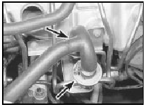
8.36 Pulse-air system check valves (arrowed) - 1.6/1.8 litre (R6A)
37 Gradually loosen the fuel inlet pipe union on the CFI unit, to relieve the pressure in the fuel system. Be prepared for fuel spray, and take adequate fire precautions. Once the pressure has reduced, disconnect the fuel inlet and return hoses. Plug the ends of the hoses to minimise petrol spillage.
38 Disconnect the throttle cable, if necessary.
39 Disconnect the wiring from the following components, as applicable.
Alternator
Starter motor
Oil pressure warning lamp switch
Temperature gauge sender
Engine coolant temperature sensor
Inlet air temperature sensor
Ignition coil
Throttle stepper motor
Throttle position sensor
Fuel injector
Cooling fan switch
Air charge temperature sensor
Engine earth strap to battery tray
40 On 1.8 litre engine models with power
steering, slacken the power steering pump
pulley bolts, then remove the alternator/power
steering pump drivebelt. Remove the pulley,
unbolt the power steering pump from its
bracket, and move it clear of the engine.
41 Unscrew and remove the top engine-togearbox bolts which are accessible from the engine compartment.
42 Apply the handbrake (if not already done), jack up the front of the vehicle and support it on axle stands (see “Jacking and Vehicle Support”).
43 Drain the engine oil into a suitable container.
44 Remove the starter motor.
45 Disconnect the exhaust gas oxygen sensor wiring connector, then remove the exhaust downpipe.
46 Disconnect the wiring plug from the crankshaft speed/position sensor.
47 Unscrew the two nuts securing the engine mountings to the crossmember. Recover the washers.
48 Unscrew and remove the remaining engine-to-gearbox bolts, noting the location of the earth strap and any wiring brackets, and remove the two bolts from the engine adapter plate (see illustration).
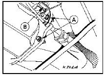
8.48 Engine adapter plate bolts (A) and crankshaft speed/position sensor
shroud (B) - 1.6 litre
49 Unscrew the securing bolt, and remove the crankshaft speed/position sensor shroud (where fitted).
50 On 1.6 litre engines, working inside the vehicle, place a wooden block under the clutch pedal to raise it fully against its stop.
This will hold the automatic adjuster pawl clear of the toothed quadrant. Disconnect the clutch cable from the release arm, and pass the cable through the bellhousing. Note the cable routing for use when refitting.
51 Proceed as shown in paragraphs 25 to 29.
See also:
Fuses, relays and circuit breakers - general information
Pre-1986 models
1 The fuses and most of the relays are
located in a plastic box attached to the
bulkhead on the driver’s side of the engine
compartment.
2 The fuses are numbered to identify the
...
Front suspension crossmember - removal and refitting
Removal
1 Remove the steering gear.
2 Support the engine with a jack and
interposed block of wood under the sump.
3 Unscrew and remove the engine mounting
nuts from the top of the mountings in th ...
Transmission fluid
Checking automatic transmission fluid
Refer to your scheduled maintenance guide for scheduled intervals for
fluid checks and changes. Your transaxle does not consume fluid.
However, the fluid lev ...
