Front suspension crossmember - removal and refitting
Removal
1 Remove the steering gear.
2 Support the engine with a jack and interposed block of wood under the sump.
3 Unscrew and remove the engine mounting nuts from the top of the mountings in the engine bay (see illustration).
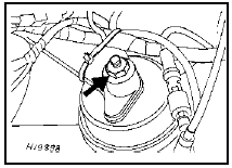
2.3 Engine mounting nut (arrowed)
4 Raise the engine slightly with the jack, and ensure that it is safely supported, and just clear of the engine mounting rubbers.
5 Unscrew and remove the nuts, washers and pivot bolts securing the lower arms to the crossmember, and pull the arms from the crossmember. Note that the pivot bolt heads face to the rear of the vehicle.
6 Where applicable, remove the brake pipes from the clips on the crossmember, taking care not to strain them, and detach any cables or electrical leads which may be secured with clips or cable-ties, noting their positions.
7 Support the crossmember with a jack, then unscrew and remove the four mounting bolts (see illustration).
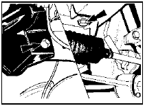
2.7 Front suspension crossmember mounting bolts (arrowed)
8 Lower the crossmember and withdraw it from under the vehicle.
9 If desired, the engine mountings can now be unbolted from the crossmember.
Refitting
10 Refitting is a reversal of removal, but bear
in mind the following points.
11 Do not tighten the lower arm pivot bolts until the weight of the vehicle is resting on its wheels. This is to prevent “wind up” of the rubber bushes which will occur when the vehicle is lowered if the bolts have been tightened with no load on the suspension. The following procedure must be used when tightening the pivot bolts. Tighten the bolt to the specified “clamping” torque, then loosen the bolt fully. Re-tighten to the specified “snug” torque and then further tighten the bolt through the specified angle.
12 Refit any cables or electrical leads in their original positions, where applicable.
13 When lowering the engine onto its mountings, ensure that the locating pegs on the mountings engage with the holes in the mounting brackets.
See also:
Fuel pressure regulator - removal and refitting
Note: Refer to the precautions at the end of
Section 1 before proceeding. A new sealing
ring will be required on refitting.
Removal
1 Disconnect the battery negative lead.
2 Depressurise the fuel ...
Rear shock absorbers (Van models) - removal, testing and
refitting
Removal
1 Raise and support the rear of the vehicle on
stands (see “Jacking and Vehicle Support”).
Place a jack beneath the rear axle tube and
just raise it slightly.
2 Disconnect the shock absor ...
Fuel pressure regulator - removal and refitting
Note: Refer to the precautions at the end of
Section 1 before proceeding.
Removal
1 The fuel pressure regulator is only used on
KE-Jetronic systems and is located behind
the fuel distributor (see ...
