Fuel tank - removal and refitting
Caution: Refer to the precautions in Section 1 before proceeding.
1 Run the fuel level as low as possible before removing the tank.
2 Disconnect the battery negative lead.
3 Remove the tank filler cap, then syphon or pump out the tank contents (there is no drain plug). It may be necessary to disconnect the fuel tank-to-fuel pump hose in order to fully drain the tank. Store the petrol in a suitable sealed container.
Saloon, Hatchback and Estate
models
4 Working in the fuel filler recess, remove the
two screws on models up to 1987, or the
single screw on models from 1987, securing
the upper end of the fuel filler pipe to the body
panel.
5 Chock the front wheels, then jack up the rear of the vehicle and support on axle stands (see “Jacking and Vehicle Support”).
6 Unscrew the two securing bolts from the left-hand tank flange, and on models from 1987, the single bolt from the right-hand tank flange.
7 Support the tank, then remove the bolt from the securing strap. Unhook the remaining end of the strap from the underbody.
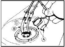
8 Lower the tank sufficiently to disconnect the two wiring plugs from the fuel level sender (pump) unit (see illustration).

9.8 Fuel level sender unit connections - Saloon, Hatchback and Estate models
A Wiring plugs
B Fuel outlet pipe
C Fuel inlet pipe
9 Identify the fuel hose locations for use when refitting, then disconnect the hoses from the sender unit and plug them.
10 Withdraw the fuel tank from under the vehicle.
11 The fuel filler and ventilation pipes can be removed from the tank by loosening the securing clips.
12 If the tank is contaminated with sediment or water, swill it out with clean petrol. If the tank has a leak, or is damaged, it should be repaired by a specialist, or alternatively renewed. Do not under any circumstances attempt to solder or weld a fuel tank.
13 Refitting is a reversal of removal, but ensure that the ventilation pipe is correctly positioned in its groove in the tank, and is not trapped between the tank and the vehicle underbody. Ensure that the fuel hoses and the fuel filler and ventilation pipes are correctly connected, and if the hoses or pipes were originally secured with crimped type clips, discard these and use new worm drive clips.
P100 models
14 Remove the cargo area (Chapter 12).
15 Disconnect the wiring plug from the fuel level sender unit, and release the wiring from the clip on the fuel tank flange.
16 Identify the fuel hose locations for use when refitting, then disconnect the hoses from the sender unit and plug them.
17 Detach the fuel pipes from their clips on the tank.
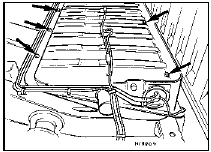
18 Remove the five tank securing bolts, and lift the tank from the chassis frame (see illustration).

9.18 Fuel tank securing bolts (arrowed) - P100 models
19 Proceed as described in paragraphs 11 and 12.
20 Commence refitting by loosening the bolts securing the front tank mounting brackets to the chassis frame.
21 Lower the tank into position and loosely refit the securing bolts. Tighten the three rear securing bolts.
22 Pull down on the front of the tank and tighten the bolts securing the front tank mounting brackets to the chassis frame when the brackets contact the insulating pads, then tighten the front tank securing bolts.
23 Further refitting is a reversal of removal, but ensure that all hoses and pipes are correctly connected, and if the hoses or pipes were originally secured with crimped type clips, discard these and use new worm drive clips. Refit the cargo area.
See also:
Fuel injectors - removal and refitting
Note: Refer to the precautions at the end of
Section 1 before proceeding. New injector
seals will be required on refitting.
Removal
1 Disconnect the battery negative lead.
2 Depressurise the fuel ...
Major operations requiring engine removal
The following work can only be carried out
after removal of the engine from the car:
a) Crankshaft main bearings - renewal.
b) Crankshaft - removal and refitting.
c) Flywheel - removal and refitti ...
Seat belts - removal and refitting
Front seat belt stalk
1 Remove the front seat.
2 Detach the seat belt stalk from the seat by
removing the two Torx screws.
3 Refitting is a reversal of removal.
Front seat belt assembly
4 Where ...
