
Throttle position sensor - removal and refitting
Note: During this procedure ensure that the sensor wiper is not rotated beyond its normal operating arc.
2.0 litre SOHC models
1 Disconnect the battery negative lead.
2 Free the throttle position sensor wiring plug from the retaining clip located on the underside of the throttle body. Disconnect the wiring plug halves by releasing the locktabs and pulling on the plug halves (see illustration).
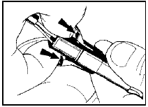
27.2 Releasing locktabs to disconnect throttle position sensor wiring plug
halves
3 Bend back the locktabs and unscrew the two sensor retaining bolts (see illustration).
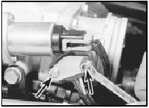
27.3 Unscrewing the throttle position sensor retaining bolts
Withdraw the locking plate and sensor from the throttle shaft.
4 Refitting is a reverse of removal, ensuring that the moulded side of the sensor faces towards the inlet manifold. The flat on the sensor wiper engages with the flat on the throttle shaft.
2.0 litre DOHC models
5 Disconnect the battery negative lead.
6 Free the throttle position sensor wiring plug from the retaining clip located on the underside of the throttle body. Disconnect the wiring plug halves by releasing the locktabs and pulling on the plug halves (see illustration).
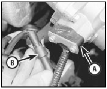
27.6 Throttle position sensor (A) and wiring plug (B)
7 Unscrew the two sensor securing screws, and withdraw the sensor from the throttle shaft.
8 Refitting is a reversal of removal, noting that the sensor fits with the wiring at the bottom.
Ensure that the sensor actuating arm engages correctly with the throttle spindle.
1.6 and 1.8 litre (R6A type) CVH
models
9 Disconnect the battery negative lead.
10 Remove the air cleaner.
11 Unclip and disconnect the sensor wiring connector, pulling on the plug, not on the wiring (see illustrations).
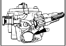
27.11a Throttle position sensor location (arrowed) on CFI unit - 1.6 litre
CVH
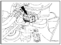
27.11b Throttle position sensor location (arrowed) on CFI unit - 1.8 litre
(R6A) CVH
12 Remove the two screws, and withdraw the sensor from the throttle valve shaft.
13 Refitting is a reversal of removal, but ensure that the sensor actuating arm locates correctly on the throttle valve spindle.
See also:
Steering wheel - alignment
1 Owing to the fact that the steering wheel is
located on a hexagon shaped steering shaft, it
may be difficult to obtain perfect steering wheel
alignment due to lack of fine adjustment.
2 It is th ...
Specifications
Torque wrench setting Nm lbf ft
All seat belt anchor bolts . . . . . . . . . . . . . . . . . . . . . . . . . . .
. . . . . . . . . 29 to 41 21 to 30 ...
Trip computer components - removal and refitting
1 Disconnect the battery negative lead
Computer module
2 Remove the single screw from the top edge
of the facia panel in which the module is
housed, then withdraw the facia panel.
3 Remove the fo ...
