Alternator - testing
Note: To carry out the complete test procedure use only the following test equipment - a 0 to 20 volt moving coil voltmeter, a 0 to 100 amp moving coil ammeter, and a rheostat rated at 30 amps.
1 Check that the battery is at least 70% charged by using a hydrometer.
2 Check the drivebelt tension.
3 Check the security of the battery leads, alternator multi-plug, and interconnecting wire.
Cable continuity check
4 Pull the multi-plug from the alternator and
switch on the ignition, being careful not to crank
the engine. Connect the voltmeter between a
good earth and each of the terminals in the
multi-plug in turn. If battery voltage is not
indicated, there is an open circuit in the wiring
which may be due to a blown ignition warning
light bulb if on the small terminal.
Alternator output check
5 Connect the voltmeter, ammeter and
rheostat as shown (see illustration).
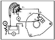
6.5 Alternator output test circuit
Run the engine at 3000 rpm and switch on the headlamps, heater blower and, where fitted, the heated rear window. Vary the resistance to increase the current and check that the alternator rated output is reached without the voltage dropping below 13 volts.
Charging circuit positive side
check
6 Connect the voltmeter as shown (see
illustration).
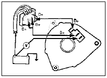
6.6 Alternator positive check circuit
Start the engine and switch on the headlamps. Run the engine at 3000 rpm and check that the indicated voltage drop does not exceed 0.5 volt. A higher reading indicates a high resistance such as a dirty connection on the positive side of the charging circuit.
Charging circuit negative side
check
7 Connect the voltmeter as shown (see
illustration).
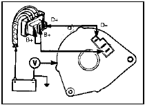
6.7 Alternator negative check circuit
Start the engine and switch on the headlamps. Run the engine at 3000 rpm and check that the indicated voltage drop does not exceed 0.25 volt. A higher reading indicates a high resistance such as a dirty connection on the negative side of the charging circuit.
Voltage regulator check
8 Connect the voltmeter and ammeter as
shown (see illustration).
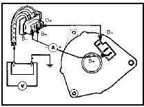
6.8 Alternator voltage regulator test circuit
Run the engine at
3000 rpm and when the ammeter records a
current of 3 to 5 amps check that the voltmeter
records 13.7 to 14.15 volts. If the result is
outside the limits the regulator is faulty.
See also:
Specifications
General
Engine type . . . . . . . . . . . . . . . . . . . . . . . . . . . . . . . . . .
. . . . . . . . . . . . . Four-cylinder, in-line overhead camshaft
Capacity:
1.1 litre . . . . . . . . . . ...
Cigar lighter - removal and refitting
Removal
1 Disconnect the battery negative terminal.
2 On pre-1986 models remove the ashtray
then undo the screws and withdraw the
ashtray housing. On 1986 models onwards,
refer to Section 21 and ...
Jump starting your vehicle
The gases around the battery can explode if exposed to flames,
sparks, or lit cigarettes. An explosion could result in injury or
vehicle damage.
Batteries contain sulfuric acid which can burn ski ...
