Engine electrical systems
General information and precautions
General information
The electrical system is of the 12 volt
negative earth type, and consists of a 12 volt
battery, alternator with integral voltage
regulator, starter motor and related electrical
accessories, components and wiring. The
battery is of the low maintenance or
maintenance-free “sealed for life” type and is
charged by an alternator which is belt-driven
from the crankshaft pulley. The starter motor
is of the pre-engaged type, incorporating an
integral solenoid. On starting the solenoid
moves the drive pinion into engagement with
the flywheel ring gear before the starter motor
is energised. Once the engine has started, a
one-way clutch prevents the motor armature
being driven by the engine until the pinion
disengages from the flywheel.
The ignition system is responsible for igniting the air/fuel mixture in each cylinder at the correct moment in relation to engine speed and load. A number of different ignition systems are fitted to models within the Sierra/P100 range, ranging from a basic breakerless electronic system to a fully integrated engine management system controlling ignition and fuel injection systems.
The ignition system is based on feeding low tension voltage from the battery to the coil where it is converted to high tension voltage.
The high tension voltage is powerful enough to jump the spark plug gap in the cylinders many times a second under high compression pressures, providing that the system is in good condition. The low tension (or primary) circuit consists of the battery, the lead to the ignition switch, the lead from the ignition switch to the low tension coil windings (terminal + /15) and also to the supply terminal on the electronic module, and the lead from the low tension coil windings (terminal - /1) to the control terminal on the electronic module.
The high tension (or secondary) circuit consists of the high tension coil windings, the HT (high tension) lead from the coil to the distributor cap, the rotor arm, the HT leads to the spark plugs, and the spark plugs.
The system functions in the following manner. Current flowing through the low tension coil windings produces a magnetic field around the high tension windings. As the engine rotates, a sensor produces an electrical impulse which is amplified in the electronic module and used to switch off the low tension circuit.
The subsequent collapse of the magnetic field over the high tension windings produces high tension voltage which is then fed to the relevant spark plug via the distributor cap and rotor arm. The low tension circuit is automatically switched on again by the electronic module, to allow the magnetic field to build up again before the firing of the next spark plug. The ignition is advanced and retarded automatically to ensure that the spark occurs at the correct instant in relation to the engine speed and load.
To improve driveability during warm-up conditions and to reduce exhaust emission levels, a vacuum-operated, temperature-sensitive spark control system is fitted to certain vehicles.
Inductive discharge system This is the least sophisticated system fitted to the Sierra/P100 range, and comprises a breakerless distributor and an electronic switching/amplifier module in addition to the coil and spark plugs.
The electrical impulse which is required to switch off the low tension circuit is generated by a magnetic trigger coil in the distributor. A trigger wheel rotates within a magnetic stator, the magnetic field being provided by a permanent magnet. The magnetic field across the two poles (stator arm and trigger wheel) is dependent on the air gap between the two poles. When the air gap is at its minimum, the trigger wheel arm is directly opposite the stator arm, and this is the trigger point. As the magnetic flux between the stator arm and trigger wheel varies, a voltage is induced in the trigger coil mounted below the trigger wheel, and this voltage is sensed and then amplified by the electronic module and used to switch off the low tension circuit. There is one trigger wheel arm and one stator arm for each cylinder (4).
The ignition advance is a function of the distributor and is controlled both mechanically and by a vacuum operated system. The mechanical governor mechanism consists of two weights which move out from the distributor shaft as the engine speed rises due to centrifugal force. As they move outwards, they rotate the trigger wheel relative to the distributor shaft and so advance the spark.
The weights are held in position by two light springs and it is the tension of the springs which is largely responsible for correct spark advancement.
The vacuum control consists of a diaphragm, one side of which is connected via a small bore hose to the carburettor or inlet manifold and the other side to the distributor. Depression in the inlet manifold and/or carburettor, which varies with engine speed and throttle position, causes the diaphragm to move, so moving the baseplate and advancing or retarding the spark. A fine degree of control is achieved by a spring in the diaphragm assembly.
ESC (Electronic Spark Control) system This system is only fitted to early “Economy” models, and comprises a “Hall effect” distributor, and an ESC module, in addition to the coil and spark plugs.
The electrical impulse which is required to switch off the low tension circuit is generated by a sensor in the distributor. A trigger vane rotates in the gap between a permanent magnet and the sensor. The trigger vane has four cut-outs, one for each cylinder. When one of the trigger vane cut-outs is in line with the sensor, magnetic flux can pass between the magnet and the sensor. When a trigger vane segment is in line with the sensor, the magnetic flux is diverted through the trigger vane away from the sensor. The sensor senses the change in magnetic flux and sends an impulse to the ESC module, which switches off the low tension circuit.
The ignition advance is a function of the ESC module and is controlled by vacuum. The module is connected to the inlet manifold by a vacuum pipe, and a transducer in the module translates the vacuum signal into electrical voltage. From the vacuum signal, the ESC module determines engine load, and engine speed is determined from the interval between impulses supplied by the distributor sensor. The module has a range of spark advance settings stored in its memory, and a suitable setting is selected for the relevant engine speed and load. The degree of advance can thus be constantly varied to suit the prevailing engine speed and load conditions.
ESC II (Electronic Spark Control II)
system
1.8 and 2.0 litre SOHC carburettor models
This system is a development of the ESC
system described previously in this Section,
but it enables more accurate control of engine
operation due to the inclusion of additional
monitoring features and control outputs.
Vehicles fitted with the ESC II system have an electric inlet manifold heater which warms the air/fuel mixture when the engine is cold, thus reducing the amount of fuel enrichment required, lowering fuel consumption and improving driveability when the engine is cold.
The heater is operated by the ESC II module receiving information on the engine temperature from an engine coolant temperature sensor mounted in the inlet manifold.
On 2.0 litre SOHC models, the ESC II module operates a carburettor stepper motor to control the engine idle speed. Using information on engine speed, load, temperature and throttle position (supplied by a switch on the carburettor), the module operates the stepper motor to maintain a constant idle speed. On models equipped with automatic transmission and/or air conditioning, additional inputs are supplied to the module to allow it to operate the stepper motor to compensate for the additional engine load imposed by the automatic transmission/air conditioning. The ESC II module also operates a “power hold” relay which allows the stepper motor to function briefly after the ignition has been switched off in order to perform an anti-run-on and manifold ventilation cycle.
2.0 litre DOHC carburettor models A development of the ESC II system is used to control the operation of the engine. The module receives information from a crankshaft speed/position sensor (similar to that described for the ESC Hybrid system), except that the sensor is activated by a toothed disc on the rear of the crankshaft, inside the cylinder block), and an engine coolant temperature sensor.
The ignition advance is a function of the ESC II module, and is controlled by vacuum.
The module is connected to the carburettor by a vacuum pipe, and a transducer in the module translates the vacuum signal into an electrical voltage. From the vacuum signal, the module determines engine load; engine speed and temperature are determined from the crankshaft speed/position sensor and the engine coolant temperature sensor. The module has a range of spark advance settings stored in its memory, and a suitable setting is selected for the relevant engine speed, load and temperature. The degree of advance can thus be constantly varied to suit the prevailing engine speed and load conditions.
ESC Hybrid (Electronic Spark Control
Hybrid) system
This system is fitted to 1.8 CVH models,
and comprises various sensors and an ESC
Hybrid module, in addition to the coil and
spark plugs. The distributor serves purely to
distribute the HT voltage to the spark plugs
and consists simply of a rotor arm mounted
directly on the end of the camshaft, and a
distributor cap.
The electrical impulse which is required to switch off the low tension circuit is generated by a crankshaft speed/position sensor which is activated by a toothed wheel on the crankshaft. The toothed wheel has 35 equally spaced teeth with a gap in the 36th position.
The gap is used by the sensor to determine the crankshaft position relative to TDC (top dead centre) of No 1 piston.
Engine load information is supplied to the ESC Hybrid module by a vacuum transducer within the module which is connected to the inlet manifold by a vacuum pipe. Additional inputs are supplied by an inlet manifold-mounted engine coolant temperature sensor, and an air charge temperature sensor mounted in the base of the air cleaner. The module selects the optimum ignition advance setting based on the information received from the various sensors. The degree of advance can thus be constantly varied to suit the prevailing engine conditions.
In addition to the ignition circuit, the module also controls an electric choke heater, and a solenoid valve which in turn controls a throttle damper on the carburettor. The electric choke heater is operated by the module using information supplied by the engine coolant temperature sensor. The heater is used to slow down the rate at which the choke comes off, thereby improving driveability and overall fuel consumption when the engine is cold. The solenoid valve controls the vacuum supply to the carburettor throttle damper. The throttle damper prevents sudden closing of the throttle during deceleration, thus maintaining combustion of the air/fuel mixture which reduces harmful exhaust gas emissions.
Note that there is no provision for adjustment of ignition timing with the ESC Hybrid system.
EEC IV (Electronic Engine Control IV)
system
2.0 litre SOHC fuel injection models
This system controls both the ignition and
fuel injection systems. The EEC IV module
receives information from a “Hall effect”
distributor sensor (similar to that described
previously in this Section for the ESC system),
an engine coolant temperature sensor
mounted in the inlet manifold, a throttle
position sensor, and an air flow meter.
Additionally, on models equipped with automatic transmission and/or air conditioning, additional inputs are supplied to the module to allow it to raise the idle speed to compensate for the additional engine load imposed by the automatic transmission/air conditioning. The module provides outputs to control the fuel pump, fuel injectors, idle speed, and ignition circuit. Using the inputs from the various sensors, the EEC IV module computes the optimum ignition advance, and fuel injector pulse duration to suit the prevailing engine conditions. This system gives very accurate control of the engine under all conditions, improving fuel consumption and driveability, and reducing exhaust gas emissions. A “limited operation strategy” (LOS) means that the vehicle is still driveable, albeit at reduced power and efficiency, in the event of a failure in the module or its sensors.
2.0 litre DOHC fuel injection models A development of the EEC IV system is used to control both the ignition and fuel injection systems. The module receives information from a crankshaft speed/position sensor (similar to that described for the ESC Hybrid system), except that the sensor is activated by a toothed disc on the rear of the crankshaft, inside the cylinder block), a throttle position sensor, an engine coolant temperature sensor, a fuel temperature sensor, an air charge temperature sensor, a manifold absolute pressure (MAP) sensor, and a vehicle speed sensor (mounted on the gearbox). Additionally, on models with a catalytic converter, an additional input is supplied to the EEC IV module from an exhaust gas oxygen (HEGO) sensor. On models with automatic transmission, additional sensors are fitted to the transmission, to inform the EEC IV module when the transmission is in neutral, and when the kickdown is being operated.
The module provides outputs to control the fuel pump, fuel injectors, idle speed, ignition system and automatic transmission.
Additionally, on models with air conditioning, the EEC IV module disengages the air conditioning compressor clutch when starting the engine, and when the engine is suddenly accelerated. On models fitted with a catalytic converter, the EEC IV module also controls the carbon canister-purge solenoid valve.
Using the inputs from the various sensors, the EEC IV module computes the optimum ignition advance, and fuel injector pulse duration to suit the prevailing engine conditions. A “limited operation strategy” (LOS) means that the vehicle is still driveable, albeit at reduced power and efficiency, in the event of a failure in the module or one of its sensors.
1.6 litre and 1.8 litre (R6A type) CVH models A development of the EEC IV system is used to control both the ignition and fuel injection systems. A fully electronic Distributorless Ignition System (DIS) is fitted, replacing the mechanical distribution of high tension voltage (by a rotating distributor) with “static” solid-state electronic components.
The system selects the most appropriate ignition advance setting for the prevailing engine operating conditions from a threedimensional map of values stored in the EEC IV control module memory. The module selects the appropriate advance value according to information supplied on engine load, speed, and operating temperature from various sensors.
The EEC IV module receives information from a crankshaft speed/position sensor (similar to that described for the ESC Hybrid system), except that on 1.6 litre engines, the sensor is activated by a toothed disc on the flywheel), a throttle position sensor, an engine coolant temperature sensor, an air charge temperature sensor, a manifold absolute pressure (MAP) sensor, a vehicle speed sensor (mounted on the gearbox), and an exhaust gas oxygen sensor.
The module provides outputs to control the fuel pump, fuel injector, throttle valve control motor, pulse-air control solenoid, carbon canister purge solenoid (where applicable), and the ignition system.
Using the inputs from the various sensors, the EEC IV module computes the optimum ignition advance and fuel injector pulse duration to suit the prevailing engine conditions. A “limited operation strategy” (LOS) means that the vehicle will still be driveable, albeit at reduced power and efficiency, in the event of a failure in the module or one of its sensors.
Precautions
General
It is necessary to take extra care when
working on the electrical system to avoid
damage to semi-conductor devices (diodes
and transistors), and to avoid the risk of
personal injury. In addition to the precautions
given in the “Safety first!” Section at the
beginning of this manual, take note of the
following points when working on the system.
Always remove rings, watches, etc before working on the electrical system. Even with the battery disconnected, capacitive discharge could occur if a component live terminal is earthed through a metal object.
This could cause a shock or nasty burn.
Do not reverse the battery connections.
Components such as the alternator or any other having semi-conductor circuitry could be irreparably damaged.
If the engine is being started using jump leads and a slave battery, connect the batteries positive to positive and negative to negative. This also applies when connecting a battery charger.
Never disconnect the battery terminals, or alternator multi-plug connector, when the engine is running.
The battery leads and alternator multi-plug must be disconnected before carrying out any electric welding on the car.
Never use an ohmmeter of the type incorporating a hand cranked generator for circuit or continuity testing.
Ignition and engine management
systems
Warning: The HT voltage
generated by an electronic
ignition system is extremely
high, and in certain
circumstances could prove fatal. Take care
to avoid receiving electric shocks from the
HT side of the ignition system. Do not
handle HT leads, or touch the distributor
or coil when the engine is running. If
tracing faults in the HT circuit, use well
insulated tools to manipulate live leads.
Engine management modules are very sensitive components, and certain precautions must be taken to avoid damage to the module when working on a vehicle equipped with an engine management system as follows.
When carrying out welding operations on the vehicle using electric welding equipment, the battery and alternator should be disconnected.
Although underbonnet-mounted modules (all except EEC IV) will tolerate normal underbonnet conditions, they can be adversely affected by excess heat or moisture.
If using welding equipment or pressure washing equipment in the vicinity of the module, take care not to direct heat, or jets of water or steam at the module. If this cannot be avoided, remove the module from the vehicle, and protect its wiring plug with a plastic bag.
Before disconnecting any wiring, or removing components, always ensure that the ignition is switched off.
On models with underbonnet-mounted modules, do not run the engine with the module detached from the body panel, as the body acts as an effective heat sink, and the module may be damaged due to internal overheating.
Do not attempt to improvise fault diagnosis procedures using a test lamp or multimeter, as irreparable damage could be caused to the module.
After working on ignition/engine management system components, ensure that all wiring is correctly reconnected before reconnecting the battery or switching on the ignition.
On some early Bosch distributors it is possible that with the distributor cap removed, if the engine is cranked, the cap securing clips may fall inward and jam the trigger wheel/vane, knocking it out of alignment. If this happens, the distributor will have to be renewed as the trigger wheel/vane cannot be repositioned. Care should therefore be taken not to crank the engine with the distributor cap removed. Later distributors have redesigned clips which eliminate the problem.
Battery - removal and refitting
Removal
1 The battery is located in the engine
compartment on the left-hand side of the
bulkhead.
2 Disconnect the leads at the negative (earth) terminal by unscrewing the retaining nut and removing the bulb. Pull off the plastic cover, and disconnect the positive terminal leads in the same way.
3 Unscrew the clamp bolt sufficiently to enable the battery to be lifted from its location (see illustration). Keep the battery in an upright position to avoid spilling electrolyte on the bodywork.
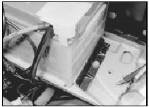
2.3 Battery securing clamp and bolt
Refitting
4 Refitting is a reversal of removal, but smear
petroleum jelly on the terminals when
reconnecting the leads, and always connect
the positive lead first and the negative lead last.
See also:
Auxiliary warning system components - removal and refitting
General
1 This system monitors the fluid levels and
front brake pads for excessive wear. In the
event of a fluid level dropping below the
specified level, or the brake pads wearing
down to the mi ...
Mixture adjustment check (Every 6000 miles (10 000 km) or 6 months)
Caution: Refer to the
precautions in Section 1,
Chapter 4, Part A or B (as
applicable), before proceeding.
Before carrying out any carburettor
adjustments, ensure that the ignition
timing and sp ...
Inlet manifold - removal and refitting
Note: A new gasket will be required on
refitting.
Carburettor models
Removal
1 Disconnect the battery negative lead.
2 Remove the air cleaner as described in Part
A of this Chapter.
3 Refer to ...
