Load apportioning valve (P100 models) - adjustment
Models before mid-April 1989 1 The vehicle must be unladen, at normal kerb weight (a full tank of petrol, but no driver or load).
2 With the vehicle standing on its roadwheels, remove the spring clip and clevis pin, and detach the spring from the valve operating lever.
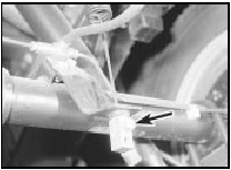
3 Loosen the locknut on the abutment block at the bottom of the spring (see illustration).

25.3 Loosen the locknut (arrowed) on the abutment block
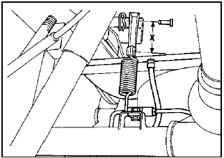
4 Slide the spring through the grommet in the bracket on the axle, until the correct “X” dimension is obtained between the centre of the spring eye and the centre of the valve operating lever eye (see illustration).

25.4 Load apportioning valve adjustment
X = 77.0 mm (3.0 in) with vehicle unladen at normal kerb weight
5 Hold the spring in position, slide the abutment block against the underside of the grommet, and tighten the locknut.
6 Attach the free end of the spring to the valve operating lever, and refit the clevis pin and spring clip.
Models from mid-April 1989 7 The procedure is as described above, but note that the dimension “X” has been revised to 92.0 mm (3.6 in) with the vehicle unladen at normal kerb weight.
See also:
Coil - testing, removal and refitting
Testing
All models except 1.6 and 1.8 litre
CVH (R6A type)
1 The coil is located on the left-hand side of
the engine compartment and is retained by a
metal strap (see illustration). It is of high ...
Body exterior fittings - removal and refitting
Spoilers and wheel arch
deflectors
Removal
1 The spoilers and wheel arch deflectors
fitted to XR3, XR3i, Cabriolet and RS Turbo
models are secured by screws, rivets and
clips, or a combination o ...
Rear anti-roll bar (Saloon and Estate models) - removal and
refitting
Removal
1 Slacken the left-hand roadwheel bolts, raise
and support the rear of the car on stands (see
“Jacking and Vehicle Support”). Remove the
roadwheel.
2 Lever the shackles from the right and ...
